Wednesday, May 07, 2008

Starting the paperwork...

We do not yet have an offical contest date for the 2008 NG-LLC. If they hold it around the end of October like they did the prior two years we are rapidly comming up to the FAA experimental permit submission deadline. So for the time being I’ve switched from aluminum to documents as my development mediium of choice. I feel this will be a lot easier this time around as I’ve already been involved with the FAA permit process.


For fun a cool picture….the business end of the vehicle taken from the flame trench of the test stand….


BusinessEnd


And one taken from inside the block house by Charles Pooley of the partial throttle test….(the wind was really blowing…)


PartialThrottle

Saturday, May 03, 2008

A tiny bit of hardware...

The vehicle is 99% complete. The only part missing is the IIP shutdown safety system. The IIP shutdown safety system calculates the instantaneous impact point (IIP) and shuts the vehicle down if the vehicle leaves the assigned flight hazard box.  The vehicle has been transported out to FAR for a static test in the near future so I don’t have a complete vehicle picture. I do have a couple of detail hardware pictures…


Openbox


The electronics box lid off and lid on….


Closedbox


The box mounts on the side of the sphere at an angle and the GPS antenna mounts on the box so it is the highest thing on the vehicle.


Lastly a short video of the jet vanes moving.


Thursday, May 01, 2008

Quick update...

Having Dad here for two weeks has slowed progress, but not stopped it.Last weekend I managed to fabricate the cwenteral control box and it is now wired. The vehicle is now basically complete. We will do a full vehicle tied down static test some time in the next week or so. This should allow us to gather some vibration data on how the IMU and GPS react to rocket vibration. After that we should start testing within the month. Its getting perilously close to the hot season out in Mojave so time is getting short.


We also need to restart the FAA paperwork process so we can do some free flights.


Wednesday, April 23, 2008

Level of commitment...Budget and Life.

Level of commitment.


A Number of people have commented on how fast things are going together. I think this reflects on the number of hours we are putting in on the project. I worked 8am to 2am Saturday and  10am to 10:30 pm Sunday.  Monday I did a full day of work at NetBurner Then spent the evening organizing some of the electronics planning connectors etc.. I went to bed at the early hour of 10:30pm. Today I got up at 6:30 am and went into work to spend 2 hours building our control PCB’s under the surface mount microscope. I then worked till 1pm and took 1/2 day off to spend some time with my wife. (More on why later in the post) Then I worked from 7:00 pm to 11:30 making servo mounts. I will do it all again Wednesday. I’m a bit tired, but it feels good. For all of you who read the blog and are not working on some dream or project, turn off the TV and do it. It will feel better than anything you have ever done.


Budget


Last year we had some cash  set aside for the project, we used most of what was set aside. This year we are funding the project directly out of current income. Last year cost almost never figured into the project. If we needed a part or a tool we had it next day.This year we are much more cost aware. Things like building the SMT board myself instead of sending them to our prototype house to have them build them at $500 a pop.  Ordering the raw PCB’s with 5 day lead rather than 2 day etc…. Now in my primary day job we send a lot (more than a million $) of work to the PCB assembly house and I could call them up and say its a personal project and they would probably assemble them for free, but that is not how I do business. All business needs to be mutually beneficial and nobody makes money giving freebies. We have no budget issue with building two of this vehicle. The second vehicle we will lighten to the maximum extent possible. Based on our design info that may be enough to do the 180 second flight on 90% peroxide. It may not. If it is not we may seek sponsorship for the 180 second vehicle development. If anyone would like to associate their corporate image with our project please feel free to contact me.(  Paul At Romeo Alpha Sierra, Delta Oscar Charlie dot COM  Here to decode )


Life


I would not be remotely as capable as I am if was not for my father. He taught me to build things, work on things and not to be afraid of hard work.  He was a career Coast Guard Pilot and retired to start a bush airline in Alaska when I was 12. He earned the Air Medal twice for daring rescues and in 20+ years in aviation in the harshest weather in the world never had a Fatality under his command. If you’ve seen the Discovery channel shows about crab fishing in Alaska, that is where dad flew for the Coast Guard. He did two tours of duty in Kodiak and one in Annette Island. Unlike todays Coast guard where pilots fly either Helicopter or Aircraft he flew both the large flying boats  and the helicopter. When my dad was stationed in the lower 48 he designed built and raced small outboard hydro-planes. He called his boats Flying splinters, hence the name for the vehicles in this project “Burning splinter”. In any case my dad is 78 and loosing contact with reality. He is to the point where he can not live alone and needs assistance with daily living. My step mother is going on a business trip and vacation to Paris for 14 days and we are taking care of my dad while she is gone. We have done this for shorter periods before, but two weeks is going to be a challenge. That is why I took the afternoon off to go hang out with my wife, for the next two weeks we will get very little personal space. I also expect that progress on the project will slow, but not stop. My dad likes to sit in the garage and watch us work. We are getting used to being asked what it is we are building…every 60 seconds like clock work.  

Sunday, April 20, 2008

Four Vanes done

Started at 10:00 am finished up at 10:15 pm. I made two new vane blanks on the Lathe, and played with feeds and speeds on the mill. Then I milled 4 good vanes. It takes about 1.5 hours each just for milling them down to thickness. Anything faster than that and they bend.


Millingvane


In anycase I have four good vanes and one actuator mount. Two of them were loose enough to press onto the bearings. Two required the freezer and heat gun approach.


Fourvanes


Monday night I should finish the four actuator mounts and get it all put together. (I still hate stainless).

I hate Stainless...

Some notes on how I design things. Some people make detailed 3D cad models of their complete vehicle. I do some dimensioned drawings, but I don’t make them a complete detailed cad model. The drawing below was my layout for the Jet Vanes.Vanefirst


This drawing was done in Rhino to scale. but as a flat 2d drawing. When the vane mount got welded to the exit cone if was about 0.1875 too far down. This caused me to redo my vane bearing mounts and redo the jet vanes as the bearing is now 0.2” farther from the exit cone. 


Once I have a scale drawing of the parts I make a simple dimensioned drawing I can take out to the shop or use to generate CNC code for the lathe. I don’t have a good lathe CAM program so all the Lathe CNC code is generated by hand or by writing a program to generate the CAM file. The CAM generation on the mill is automated from the drawing.


VaneDraw1


This is the drawing for my new corrected vane. I got up this morning and went to two places, IMS to get more 316 stainless shaft to make vanes out of, and to Marshals Industrial hardware to get some more carbide end mills to cut the stainless. So after working from 8 am to 1:30 am I have the following:


StainlessCarnage


The three parts on th left are not yet destroyed. All the parts on the right are toast in various ways. The four that look relatively complete are done to the original drawing and are now the wrong dimension. Some of the bad ones have the wrong bearing dimension (They are loose on the bearing), I had a problem in my hand crafted lathe code where I made 4 exact errors…. The other two are the result of milling problems, the new carbide bits I got today just aren’t lasting. MY last set that I ordered from MSC would do two vanes before they were dull, the ones I picked up today last for 1/2 of a vane.  So since I went through all my carbide tooling I though I’d try a big 3/4 TAIN coated HSS end mill, real slow…. The one in the middle left with the notch is the result of that experiment. The bit cut just fine … for awhile then it suddenly welded it self to the work piece and when I based the mill to recover it bent the vane. The three parts on the left are done with the lathe work (sort of) and now need milled. The one on the bottom left that looks like it was gnawed by a rabid squirrel is the result of trying to part off the  vane and having the parting tool die. I really should not be parting solid stainless on my Lathe its just not rigid enough, but I don’t have the shop space for the proper tool, a metal cutting horizontal band saw. I even tried the Armstrong method, I bought the highest quality hacksaw blades I could find at home depot and after two strokes the stainless removes all the teeth. 


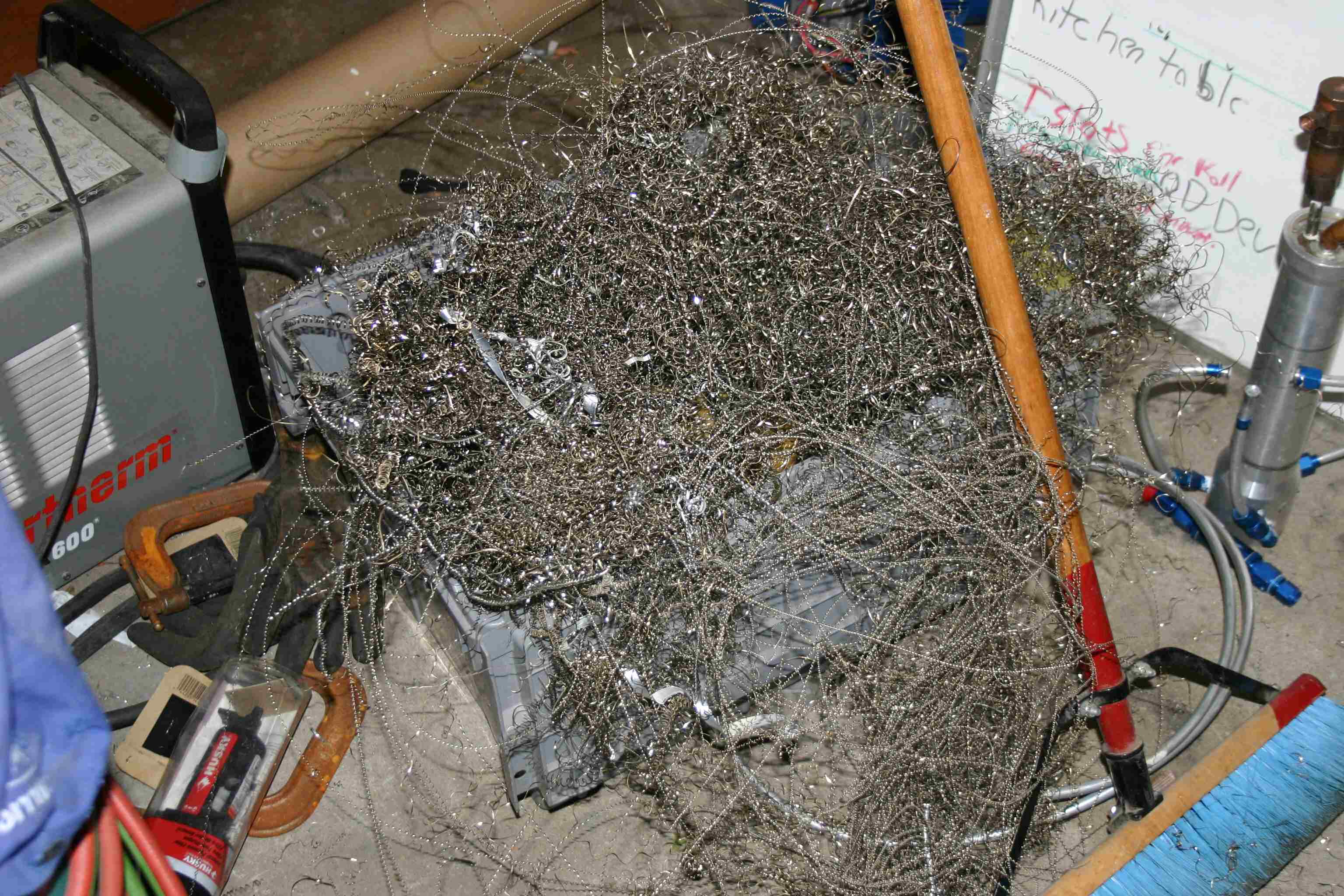
Lastly the lathe makes miles of razor sharp stainless turnings, They get tangled with everything and cut you if you just look at them crooked.Stainlessknives


 As a general rule I don’t wear gloves near machine tools, its a good way to loose your hand. So in the last 24 hours I’ve bled from 5 of my 10 fingers.


Cutfinger


The vanes are bieng used in a hot oxygen stream so I need the maximum oxidation resistance, otherwise I’d use 303 stainless a lot easier to machine. Did I say I hate Stainless?  Hopefully today will go better…


Friday, April 18, 2008

Plumbing complete

The vehicle plumbing is complete. I should have the Jet vanes finished Saturday. That leaves wiring. We weighed the vehicle as is and its  96 lbs . We have less than 5 more pounds to add (not including payload) and we should be a full 25% under our target weight. We can meet our 90 second hover with an average achieved ISP of 79 seconds.


Without payload running 90% peroxide we should be able to hover for 160 seconds.

Monday, April 14, 2008

Best of Days Passed Hydro

PassHydro


Minimum Structural Hydro 1.2  1.2x 300 = 360 PSI, we went past 360. Design burst is more than 600 design SF 2.0 we can now start some actual testing, the vehicle will never be presurized with humans in the safety hazard zone. We will build a second vehicle with better weld prep and hydro that to a higher pressure.  for now we can do a lot of testing with tank pressure < 240 PSI.

Sunday, April 13, 2008

Update...

Congratulations to Cal State Long beach/Garvey Space, (The team members overlap a lot so I’m not sure which group was the lead, the rocket I saw pictures of had decal for both) I heard  they successfully flew a Lox Methane rocket this weekend.   (I think this is the first ever) This adds to that groups firsts:


  • First Flown composite Lox Tank.

  • First flown aerospike

  • First flown Lox Methane.


For Unreasonable Rocket we think we were able to repair the tank. We will do a new Hydro test on Monday night or Tuesday. We re-welded the entire seam with a lot more heat. In any case I’ve been investigating new tank concepts and I’ve found a tank concept that will be stunningly light for peroxide. We may work on this for the 180 second vehicle. 


I finished machining my first Jet vane and shaft out of billet stainless (I hate machining stainless) I’m going to try to finish a couple more tonight. The Lathe work is done on all four ,the mill work still needs done on three of them.


OneJvane


I hunted down the cause of my helicopter crash and resolved that. I had a gain constant off by a factor of 2 when switching from position hold mode to position  and altitude hold mode. I flew it again and it flies nicely, but the tail rotor started acting really flaky. It would drift all over the place and not hold heading. Something is wrong, but all my field diagnostics gave me no info. I’m a bit stumped. I’m tempted to give the computer direct tail rotor control and remove the tail rotor gyro using only the IMU for tail rotor control. Just Like Jack did a while ago…

Tuesday, April 08, 2008

Best of Times woorst of times..


Tonight we went from vehicle ready to wire…


SphereVehicleActual


To almost passing hydro test… For our operating pressure of 300 PSI the FAA minimum is 360 PSI, the sphere has a design burst of > 600 PSI, we got to some where between 350 and 370  we wanted 375 to 400. (We will never presurize in the presence of humans.)


TankFail


Its clear we did not get enough penitration, the weld only went ~half way through the base metal. Very discouraging.

Sunday, April 06, 2008

Quick Update...

The Landing Gear main legs are done after the first attempt did not work, the orings leaked and the retaining ring was not strong enough. We will get the gear brace mounts welded up on Tuesday, it shoul dbe sitting on it’s gear by mid week. We had hoped for a full vehicle static fire on Saturday, its looking unlikely.


Crashed the helicopter again, only very minor copter damage, but destroyed on of the expensifve LiPo battries. Went into a weird pitch and roll osscilation.  Probably need to do some gain tuning. broke one blade and destronyed the battery, otherwise undamaged.

Monday, March 31, 2008

Sphere vehicle rough rendering

SphereVehicle


There are a bunch of details missing such as braces for the motor,electronics boxes, jet vanes vents etc…. but it’s aproximatly right.

Thursday, March 27, 2008

Autonomous Hover Video


Not produced to the best quality, but it shows the helicopter hovering,


both in manual altitude and full altitude hold modes..


Wednesday, March 26, 2008

Autonmous Hover

I just finished flying out an entire Trex battery pack in 3 axis autonomous position hold hover. (Altitude was still manual) I set the reference position landed, moved the helicopter and it returned to the commanded position from 10 yards away with displacements both north and east of target. Hover never seemed to deviate by more than 1.5m from center. At one point the hold position moved about 1m in a pronounced step, I have not analized the telemetry yet, but I assume this was a change in the GPS sats tracked. This was done with the Hemisphere GPS in 20Hz update mode, but without the differential corrections. I will attempt to acquire video to bring with me to space access. I’ll post telmetry details later tonight.  

Saturday, March 22, 2008

More Pictures....

Tank_Complete


The whole assembly is upside down.


From Top of picture to bottom…. Motor (not yet welded together) Big stainless check valve, main valve, tank(100% welded) plastic bucket. We will provide some pictures of the tanks in process as our welder Bob took some pictures, but I don’t have them yet.


GearMountDetail


Detail shot of the gear mount. (Upside down) 


Detail shot of the Tank Top…


Tank_Top_Detail 


So far the tank is about 5% over the “Spread sheet” target weight and the motor is 50% under the spread sheet SWAG, In total all parts we can weigh are comming in under the target weight.


The motor exit cone needs to be shortened a bit and the main chamber will shrink as we have a really parinoid L*. We are missing one small fitting for the Catalyist injector fittings or the whole motor would get welded together today. The local indusrtial hardware store is usually open on Saturday, but they closed for Easter.

Monday, March 17, 2008

Data Results

We went back out and reran the test after the purple nighmare.


Decomp_3_16


Here is the pressure data from the decomposition test. Note that the chamber pressure dropped off more than the feed presure did this makes me think the excess permangnate at startup had a positive effect and we would benifit from from some kind of screen in the chamber to hold the reactant products longer. Note how the feed pressure drops off rapidly when the peroxide runs out.


Decomp_3_16_temp


Here is the data with thermocouple voltage data added. One channel did not work at all and the data is very puzzeling. TC1 (not shown) is at the exit with TC2,TC3,TC4 getting closer to the Injector end. Either I have my wireing notes wrong (possible) or I don’t understand the data.Why would the thermocouple in the middle be lower than the one on the ends?I have not calibrated the thermocouple data, its displaying scaled RAW A/D counts. From the noise its clear I need to work on my TC amplifer some more.


Here is the video from the test series


Sunday, March 16, 2008

The Purple Menace strikes back.

A quick update, we’ll post videos and more info in a couple of days. We went out to FAR to work on the site and run a quick repeat of our decompoisition test. When we ran it a flxible stainless line from the  permangenate tank to the motor failed at the fitting spraying permangenate everywhere. We had gotten a bit lazy and did not remove the tools generator etc.. from the vicinity of the test stand. SO everything involved with the test is covered in fine purple goo. We only used 1 liter of permangenate ,but 1 liter covers a truely amazing amount of area. The leak was at about 300 PSI so we covered  everything in a 35 foot radius with purple goo.  I can’t find the reference, but somewhere I’ve seen a dilution ratio of 10000:1 specified for making the purple go away.I can personally vouch for that number. I can also vouch for the warning one of the Arocket chemists gave me that vitamin C solution is exothermic with concentrated permangenate. A Vitamin C and  soaked shop rag used to wipe down  permangnate splash will end up smoking.

Friday, March 14, 2008

Progress...

This morning I had a conference call with the FAA to talk about getting started again.  With the rapid progress we are making on the simple vehicle there is a very real possibility that the ability to get a burn time waiver will become a limiting issue. So I need to go back into paperwork mode, the most fun part of the project!


Based on some feedback from John Carmack and some personal experiences trying to get Large fittings to seal we are switching to sanitary fittings for all of our large plumbing. We have always wanted to use a butterfly valve for better throttleing and less hysteresis, this is hard to do with lox as no seal material is soft at Lox temps. With peroxide its a bit easier, we found a 1 inch butterfly valve with built in sanitary connections and hydro tested it to 500 PSI. It held fine and operated correctly. Its nominal commercial rating is 150PSI, we are going to run it to 300 PSI. My son designed and machined a two peice aluminum housing to hold the valve and connect one of our servos to it.


Butterfly


Its a fast 1” valve.


How come we spend so much time on valves? Here is the dual igniter valve we made last year…


Dualvalve


This weekend we are going out to FAR to rerun the L* test with sodium permangenate. We are also going to do a bunch of site improvement work, trenching, running power and data wires and boring the big hole to put the foundatiuon in for our tether crane.


Stunning Rocket news: at 8:10 PM everything is packed and I might get a full nights sleep before a test!

Sunday, March 09, 2008

Helicopter Tanks and Shuttle

HelicopterI’ve got the helicopter flying in attitude hold more, but I have not yet turned on the postion hold software. I want to review the data from an atitude hold flight before turning on the position hold. So I went out and flew the helicopter again today. Data records fine at home, it records fine according to the lights on the recording unit, alas when I get home and look at the SD card no data. Arghhhhh….


Tanks We did a lot of prep work on the tanks today, we figured out what brackets, fittings etc… need to be welded on. I also machined some Aluminum sanitary fittings for the main propellant line. My  mcMaster sanitary parts arrive on Monday so I’ll see how well I did with the aluminum ones on Monday. One of the hemispheres has a stress crack that goes all the way through. I hope this is not an omen for the whole set of 6. I think I can probably stop drill the cracks, grind them out and weld patches over them, but its less than ideal. We’ll save that hemisphere for last.


Shuttle One of my long term really want do to items is to watch a shuttle launch. I’ve seen it land 3 times (including the very first time), I’ve never seen it launch. Tuesdays launch will be a night time launch and should be quite spectacular. I came real close to hopping on southwest and flying out to florida to see the launch. I would have cost me $800 two days of works work and at least one day of Unreaosnable work and in the end I decided that I really want the time to work on Unreasonable. We are so close to having every thing come together for the new 90 second vehicle. So I’ll try to be less impulsive and plan ahead to go see the next launch.

Saturday, March 08, 2008

Parts

The new 1” (or possibly 3/4”) valve mechanics.


Bigvalve


The baffels for the new tanks… they still need to be trimed, fitted and welded.


Rawbaffle


Parts for the potential off the shelf monoprop chamber only welding required… (Will probably up the base tube size for a shorter chamber.)


Otschamber


Wednesday, March 05, 2008

Data and Plans

Based on a lot of discussion with the chemists on Arocket its clear that the potasium catalyst was about 1/7th as active as the sodium catalyst I’d designed for. So we need to rerun the test when we get our sodium permangenate. We have it on order from two different sources. I finally reduced the data from my test and I got zero thermocouple data. I need to work on that. We hope to rerun the test on the 14th.


Here is that data I did get.Peroxide_3_1


Several things to note. first off my pressure regulator is not healthy. Its hitting the correct final pressure, but it is not happy doing so. Second according to the CV calcs I did the 1/2 inch valve should have about 10 PSI drop at full flow, it clealry had 150 PSI of drop. This could be because chamber pressure did not come up due to incomplete decomposition, but in that case I would have expected a larger injector drop due to too high of flow. Toward this end I spent the last two nights fabricating a fast 1” ball valve controller, I’m waiting for one more McMaster part and I’ll test it Thursday night. 


We are currently fleshing out the details of our 90 second test vehicle. We made baffles and parts for welding the tanks together. I’ll provide pictures when the tank starts going together. The last parts should be back from the Water Jet Cutters Friday. We are going to use AN fittings for all the plumbing smaller than 3/4 and probably sanitary fittings for the larger plumbing.  We have one area where the two Pauls do not yet agree, we can’t decide if we are going to use attitude thrustors or jet vanes. For the monoprop the jetvanes are clearly a win, but our longer term plans include making the vehicle a bi/tri prop by adding fuel to the peroxide and getting more performance. The bi/triprop  is a bit warm for jetvanes. It probably means we need to use some kind of exotic refrectory metal or ceramic. The bi/tri prop is the  current path to the 180 second prize.


For the Monoprop the safety system will be easy, we will add one small normally closed  valve to the liquid catalyst. As you can see in the video the thrust stops abruptly when the catalyst is all gone. (You can also see this in the chamber pressure trace above)  The bi/tri prop is more problematic as one might expect the biprop to keep going even if you turn off the catalyst.  If all goes well we expect a compete monoprop vehicle in about 6 weeks. We have all the long lead parts in hand. The current design is really really simple


I’ve glossed over a whole bunch of work… cat pack research, small thrustor chambers, learning about peroxide chemistry,high temperature ball bearings,  big servos, off the shelf source  thrust chambers, work on the helicopter, etc.. etc…


I’ll present the details of the 90 second monoprop vehicle design at Space Access. We will be at Space Access for all three days.If you are a space fanatic, and enjoy hanging out with three sigma nerds you can’t beat space access. 

Monday, March 03, 2008

Testing new Blogtools

To date I’ve been doing all my blogging with the blogger online tool. It is really limited, today I’m trying a desktop blogging tool. I’m hoping it will make things a little easier.


PaulaPeroxideTighten


This picture was taken by Ben Brockert, one of the Masten guys that came out to watch the test. As he says ("Where's Waldo" bonus: find Paul's foot) Also notice the wind swept hair and the flapping tee shirt. It was REALLLY blowing.


Here is the You tube video embedded in the blog. The tool I’m trying is blogjet.

Sunday, March 02, 2008

The Purple Menace

Saturday we went out to FAR and ran a test to determine Peroxide decomposition L* for a liquid catalyst. We were unable to get Sodium Permanganate for this test so we ran it with Potassium Permanganate. This results in about 1/4 the amount of effective catalyst. The end result is that we did not get full decomposition. The peroxide was still cloudy at the end of the tube. We did however fully check out a new test stand and data collection. All the parts worked correctly. A lot of people have told us that Permanganate makes an insane purple mess. Part of this test was to determine if we could handle this "mess". Thanks to a suggestion on Arrocket we mixed up a saturated solution of Vitamin C powder and that cuts the purple menace, making cleanup a non event.In the test setup we had insufficient permanganate so 100% of it was reacted in the engine leaving the engine perfectly clean. The only purple goo was from filling the cat tank.

The Last time I was out at FAR it was really pleasant. Nice lite breeze, moderate temperatures in the liow 70's and generally jerust a pleasant environment. So I convinced my desert hating wife to come with me this time. This must have angered the mojave deity as the wind was blowing so hard it felt like you were being sandblasted. The wind was blowing so hard that 2.5 GAL distilled water jugs 2/3 full were blowing over. It actually complicated the peroxide handeling, as we were in a blowing catalyst blizzard. It also made the personal protective gear hard, as the wind would blow a full face shield off in an instant. Also when you get peroxide on you it stings/burns, the blowing sand/rocks/boulders also sting. We were forever walking up to each other and saying any white spots on my face? The answer was always no, so we had no peroxide issues, but the sand was really unpleasant. There was a discussion of what was worse the wind or the 125degree heat we've seen on the site. Most preferred the heat, then John, who lives near FAR, said why do you think you would not have both? That pretty much ended the what if discussions involving mojave weather.


I've posted a a quick youtube video of the test. As a side note this test went from a concept to a test including assembling a test stand, fabricating a test motor and custom thermocouple electronics in 7 or 8 days.

Tuesday, February 26, 2008

Hardware, Rocket Hardware

If I learned any lesson from last years attempt its KISS keep it simple stupid.
A 4 engine vehicle with 39 valves is not going to fly reliably. Toward that end this years vehicle is going to be much simpler. Today I got a package...


The more I work on this stuff the smarter John Carmack gets... these are 6 5086 spun aluminum hemispheres from AMS industries.


They are 30" ID 0.1875 inch at the base 0.171 thick at the edges. 19 lbs each half. This should conservatively give me a burst pressure between 600 and 800 PSI. I'm shooting for 500, so I may lighten them a bit. The edge thinning is a lot less than AMS said it would be so I could have gone down a size in the thickness and saves some weight.

Given KISS what is the simplest system that will do the level 1 prize?
A Peroxide monoprop.
Everyone who works with peroxide spends inordinate time playing with cat packs. So I'm going to test a liquid catalyst like the Germans used 65 years ago. Using 85% peroxide I'm well under the melting temperature of 316 stainless so no cooling is needed I can just use a stainless chamber. I can also buy No clog spray nozzles in 316 from McMaster Carr and use off the shelf spray nozzles. The big question I have is with a liquid catalyst, what do I need to L* or chamber length? So I got a simple experiment I hope to run this weekend, its a long Stainless tube with 316 stainless pipe fittings welded in one end. In the pipe fittings I screw in off the shelf low clog spray nozzles and install thermocouples down the length of the tube to see what length is necessary to get maximum decomposition temperature.

Monday, February 18, 2008

Bittersweet day

My son and I spent the day cleaning out the garage in anticipation of getting back to rockets.
Part of this involved taking the carcass of the origional Unreasonable rocket to the aluminum scrap dealer. We both agree that a 4 engine vehicle is just too complex, but its still sad to take brackets, fittings and tanks one worked hundreds of hours on back to the scrap dealer.

Saturday, February 16, 2008

Progress and thoughts...

I flew the helicopter in attitude hold mode today.
It worked perfectly. the autopilot flys a lot better than I do. On flight #2 the commercial off the shelf RC regulator failed and the servos acted very erratic.I set it down with no damage. More debugging Sunday.

My son and I spent the day at FAR, we went out to clean up our storage space, work on the site and watch a large 5K liquid test firing. The work on the site is the real sexy part of rocket development. I spent my morning repairing the outhouse door jamb and installing godzilla's own door closer. Maybe the Mojave winds wont rip the outhouse door off, again.

After a full day of checkout the large test was a no light with a frozen LOX valve. We were not involved other than as spectators. My son has been working with some people doing peroxide rockets of various forms,and the grass on that side of the fence looks a lot greener.... Use cheap nitrogen for a presurant gas, all your valves and plumbing are at room temperature, dense, reasonably clean. Possibly auto igniting in bi-prop mode after decomposition.... hummm....

Monday, February 04, 2008

Quick Update

I've been very busy with "Other" mostly trying to catch up on work. I've been doing some work on the helicopter and I've flown it a few times, but no big news to report on that front. I've started testing with the DGPS and I've come to the conclusion that I need better antennas to make the RTK work. My one successful RTK test with the antennas on my roof took 46 minutes to resolve the integers, and then the solution was accurate to within 6" at 10Hz for 10 hours. The average RTK solution between the antennas was 20.02" with actual measured truth being 19.75". My son has come back down from the bay area to work on some rocket projects, both unreasonable and other..... I can't talk about "other" other than to say it is a paying gig. I'm glad to have him home.

I also find it frustrating that its sunny all week when I can't fly, then it rains all weekend where I can't fly.(Actually it stopped raining during the super bowl and I choose to watch that) This week is not going to be "unreasonably " productive as I have a lot of stuff going on.

Monday, January 28, 2008

Sunday, Loops and Simulation

The Simulated weather for Sunday was Rain all day. The Reality was that after 10am it did not really rain again until 4:00pm. So I went flying. I'm currently working on altitude hold, but the wind was really gusty gusting from 5 to 20mph. A helicopter takes less energy to fly when moving than when it is hovering. If you try to hover in one spot with gusty winds the helicopter balloons up and down as the wind speed increases and decreases. This makes it very hard to sort out the altitude hold loop as you are never sure if the up and down is wind or oscillation's. I could hover lower and get a better handle on how the altitude loop gain is but until I have it hovering at high (recoverable) altitude I'm not going to play with the altitude hold down low. The altitude hold will have to wait until a calmer day.


So since I could not do altitude hold I thought I'd work on heading hold. In flying around with the magnetic heading hold engaged the helicopter seems relatively stable but the tail wandered a few degrees each way. I always thought that it was some local magnetic variation, that may contribute, but in looking at the data the tail target vs actual error is often 3 to 6 degrees and it wanders a bit. It seems to hold an offset. The standard way to fix this in a control loop is to add some integral error term and the result is The oscillation's you see on the left. So I turn down the I term (to 5% of the P term) and turn up the D term and its better, but still not ideal. You can still see some 3 to 4 second oscillations when steady and a fair bit of overshoot when perturbed. I'd been doing the default PID tuning of turning the P gain up to the point where it just starts to oscillate and taking the Ziegler-Nichols values you can find on the web. I conceptually understand what is going on, but this is straining my control system theory. (My only official control theory class was all done as laplace transforms in 1983) Early in my professional career(1985 to 1991) I did a fair number of analog and mixed analog/digital control systems, but always with a adult supervision from a controls person. Since 1991 I've mostly been a software coder. So in trying to relearn all of this I have a several specific questions that I'd love have any lurking control theory guys help me with.

Most control theory books, articles and tuning discussions assume you have a linear plant. In reality most of my "Plants" will be integral in nature. IE I do not control the thing I'm trying to close the loop on directly, I really control the acceleration or rate. So there are one or two physical integrals between my control input and the thing I want to control. See the example to the left.
If I just close the loop around the whole thing, its going to be really unstable. So my plan was to have Target Position yield Target Velocity Target Velocity yield target Pitch and Target Pitch yield Pitch Rate. This would have hard limits for each intermediate step. IE max velocity will be 5m/sec, regardless of the position error. Clearly every intermediate step in this will have a proportional gain term, any advice on which ones should have integral terms and when I should reset the integrals to zero?


I'm also struggling with a stupid simple question I have about PID terminology. You can express a PID as

control= P*(error+I*integral+D*difference_or_rate)

or You can express a PID loop as

control = (P*Error)+(I*Integral )+(D*difference_or_rate)

When you look at the standard Ziegler-Nichols chart :
for PID P = .6Gu I=2/PU D=PU/8 Is this for the first form or the second? When you measure Pu I assume Pu is the oscillation period in samples (this is a discrete system), or have I made a wrong assumption here?

Lastly is the guidance for standard linear PID tuning even valid for this sort of plant? If not can one provide some guidance on tuning such loops?

Sunday, January 27, 2008

It Never Rains in Southern California


Notice the Probability of precipitation line...90% at 1AM 100% for the rest of the day. No FLying today.

Saturday, January 26, 2008

Pavlov's Pilot

After two outings where I hit the altitude hold switch and I crashed, I was hesitant to test again. I reluctantly went out to test fly the helicopter today and on the second flight I got up the courage to hit the altitude hold switch and things seemed to work. I failed to get data from the second flight for some reason, probably has to do with the software in the Telemetry box not logging restarts correctly, but I'm not exactly sure why I got no data. I'm ready to test again in the morning.

Last Crash

The last crash was a bit violent. You can see the crushed tin that held the formerly working GPS.


I did not take a picture of the crashed helicopter, but here are some of the broken pieces extracted from the trash.


I was planning to replace the GPS with the new smaller differential capable GPS so I
packaged that in an altoids tin, its about 1/3 the size of the old GPS.

Here it is rebuilt and ready to try again. To get a concept of the amount of work, the main frame on the helicopter is flat carbon fiber plate, in the broken pieces picture you can see that both side plates were broken.

Friday, January 25, 2008

Another Altitude hold crash...

I crashed again this morning before work. I know that I had all the mode switches in the right place in the right order. This is very frustrating!!! ARGHHHHHHH
A brief look at the data implies that the Gain was just WAYYYY to high, but it should be identical to the flight gain where the helicopter did perfect altitude hold. This time in addition to th parts listed form the last crash I broke the tail boom and side frames. I see at least 8 hours of work to be flying again. I'm going to have to find a way to sneak up on this one as its getting expensive.

Thursday, January 24, 2008

New GPS boards...

The adapter board to wire up the new GPS arrived on Tuesday,
I finally got to assemble them today. I've got to make a shield can for the helicopter and an antenna mount for the Telemetry suitcase and I can start testing with the differential GPS. Tonight the GPS is hooked up to the antenna on my roof and I'll record 12 hours at 10Hz and see how much things move around. the picture below shows that my house has moved 4.36M in altitude and 1.29 and 2.77 in lat and lon since I started the GPS recording positions 4 hours ago.
Not too bad for an unaided GPS iin the rain partially under a tree.

Some simple Trig

Last night after I finished reassembling the helicopter I did some software work on the helicopter simulator . The sim is a full 3D 6DOF helicopter simulator with display. I downloaded it about 9 months ago and it works well. It was part of the source forge helicopter autopilot project. I've been using it to develop control laws for the real helicopter. Last night I changed my simulator control laws from having yaw always north facing to putting in a full transform from North, East to Forward Right for the position and velocity feedback loops. My helicopter sim now flies the full NG-LLC flight profile while doing slow 2 deg/sec rotations the whole time. It all works so the next stop for this code is the "real world " helicopter.

Wednesday, January 23, 2008

Crash Gordon and the Helicopter(s).

My Son came down from the bay area to visit this weekend so I did not get much unreasonable work done.

Crash #1 On Sunday we were going to a play in balboa park and I had 30 minutes to kill. so I was flying the little fully manual trex 450 in the driveway. While I was doing this my wife came out and started moving the garbage cans toward the curb. I was in the way so I landed the trex next to the truck, shut down and preceded to take off the neck strap on the transmitter so I could help with the trash, in the process of doing this I hooked the throttle hold switch with the neck strap and the helicopter spattered itself all over the side of the truck. Its a good thing the trash cans were not yet at the curb, I had additional material!

Background for Crash #2.
On the last reported test flight altitude hold worked very well, but I had not yet tested clmb and descent. So I made two minor software changes, I added limits to the vertical velocity. (Vertical velocity had just been the differential term in the alt hold PID, but I spluit that in half so I could explictly limit vertical velocity. )I reprogrammed the mode switch to facilitate testing this. The Mode switch has three settings mode 0, 1,2 Mode 0 has always been manual.
Mode 1 was rudder heading hold, mode 2 was Altitude and Rudder hold. I changed this so both Mode 0 and Mode 1 were manual and Mode 2 was automatic Rudder and altitude.
I also recorded the target Altitude , Heading and initial collective value when going from mode 0 to mode 1. The idea being that I could set my target altitude by toggling from 0 to 1 then manually deviate from this position and go to it when switching to mode 2.


I went and test flew this combination on Tuesday Morning. In the process of adding the velocity limits I'd changed a feed back sign and altitude hold went the wrong way... I started above my target and when engaged the helicopter accelerated up at ever increasing rates. I tried this twice and figured out what was wrong and called it a day after 45 seconds of flying.


I changed the software sign last night and went out this morning to test the change.

Crash #2
I did my usual preflight routine I made sure that all the controls on the helicopter moved in the correct direction. (In past S/W version this was also a test to insure I was in mode 0, because in mode 1 rudder would not respond) So I brought the helicopter to a stable hover about 30 feet in front of me at about 15 to 20 feet of altitude. I then proceeded to flip the mode fro0m mode 0 to mode 1, alas it was already in mode 1 and I went to mode 2. Realize that while manually flying a helicopter you can't look down at the transmitter to check switch positions. It must have gotten bumped into mode 1 while I was hooking up the main propulsion battery or starting the video camera. So when it went from Mode 0 to Mode 1 it was at altitude 0 and full down collective. So when I went to mode 2 its target altitude was 0 and its initial guess for the collective position was full down. This is a fully acrobatic helicopter so full down collective is at least 3 negative gees. Before I could react the helicopter was on the ground, hard.

Broken parts: Both skids,flybar, flybar paddles, both blades, GPS antenna mount, one blade grip ball end, battery tray and the Jesus bolt. (the bolt that holds the main rotor to the airframe is called the Jesus bolt) total damage about $120.00 with the majority of that being the blades.
I had spares of most of the parts. Tonights task was to reassemble the helicopter. Its done, but not tested yet, I'm letting the glue on the GPS antenna mount dry while I type this.
(After glue dried tested all electronics and systems all check out ok, ready for blade tracking in the AM weather permitting.)

Saturday, January 19, 2008

Two controls down, two (hard ones )to go

I flew the helicopter this morning.
First time with altitude hold. The Autopilot does a MUCH better job of altitude hold than I do. Next Up (Sunday?) Pitch and Roll. this was also the first flight with airborne video, I'm not going to post the video because the camera was oscillating up and down and watching it makes one sea sick.
(I also pointed it too far down so 8 minutes of the dirt in a dirt parking lot would not be worth much.) I'll try to improve the angle and the mount before the next flight. The Ultimate Camera Helicopter would be: (http://www.bergenrc.com/ObserverTurbine.php, or maybe http://www.bergenrc.com/Observer.php)

The next steps will be

1)Pitch and Roll to Elevator and Alieron PIDs, where the RC system provides commanded pitch and roll angles.

2)Vforward and Vright velocities provide Desired Pitch and Roll where the RC system
provides desired Vforward and Vright.

3)GPS position hold -> Gives desired Vnorth and Veast ->yielding desired Vforward and Vright.

Friday, January 18, 2008

Smart helicopters...

A good read on automating a helicopter.
http://sun-valley.stanford.edu/papers/Conway:95.pdf

Control Stratagey

The four things I can control are: Rudder, Collective, Elevator, Aileron.

My scheme for control is to use a set of PID loops.
Most likely some of these will only have P gain, but the concept is to use the following:(Copied from code) The PIDs marked with * in the comments will be different in the rocket.


OnePidElement Yaw_to_Rudder; //Takes IMU yaw and drives rudder *
OnePidElement Alt_to_VSpeed; // target altitude drives desired vspeed.
OnePidElement VSpeed_To_Collective;// desired vspeed drives collective.*
OnePidElement Pitch_To_Elevator;//desired pitch drives Elevator.*
OnePidElement Roll_To_Alieron;// desired roll drives Alieron.*
OnePidElement V_Forward_To_Pitch;//desired Vforward drives pitch.
OnePidElement V_Right_To_Roll; //desired Vright and drives roll
OnePidElement Long_to_V_East; //desired Longitude and drives VEast.
OnePidElement Lat_to_V_North; //desired Lattitude and drives VNorth;

And one more conversion function:
void ConvertDirection(double V_North, //Desired V_North input
double V_East,//Desired V_East input
double Yaw,//Current True YAW corrected for magnetic deviation input,
double &V_Forward,// Converted V_Forward target out
double & V_Right, //Converted V_Right target out
);

OnePidElement is an object that holds the a PIDGainConstants object and the current integration state.

The Yaw to rudder , Pitch to Elevator and Roll to Alieron PIDs will be run for each IMU sample.
All other PID's will be run for each GPS data set.
I'm not planning to integrate the accelerometers. (Yet)
An example would be:
Elevator=Pitch_To_Elevator.DoServoPidAdjust(target_pitch, imu.pitch , imu.x_rate);

Each OnePidElement contins a PID gainObject that has the following gain limit elements:
double p_gain;//Proportional Gain
double i_gain;//Integrator Gain;
double d_delta_gain; //Sample to Sample delta gain
double d_meas_gain; //Rate as measured by IMU or GPS
double max_i_windup;// Maximum integrator value limit.
double min_i_windup;//Minimum integrator value limit.
double max_out_limit;//Maximum allowable value or adjustment
double min_out_limit;//Minimum allowable value or adjustment

In fact I have two D terms in my PID. One is change in the sampled values (IE the delta term from sample n-1 to n) and the directly measured rate. The directly measured differential/change rates are from the IMU and GPS.

I'm currently working on the interface to selectively change these PID constants in flight. This might be easier if I switch to a two person operation, one to fly the helicopter and one to twiddle the gains. For Now I'm just going to work one axis/ PID at a time.

Above all of this is the rather simple executive that generates the sequence of target lat,lon and altitude. At this point that excutive just tried to freeze the vehicle in space when activated. (IE use the current Yaw, Alt ,Lat,Lon as the target)

(Sorry for the crummy code formatting blogger does not seem to like formatting code in a reasonable way)

Wednesday, January 16, 2008

The urge to have a science project.

One has to be careful that time and money are allocated correctly. For several years I've been contemplating developing a lower cost GPS Differential/RTK system using commercial receivers.
While an open source solution would be a nice to have, it really makes no sense. I can purchase off the shelf differential GPS solutions that are inexpensive given any realistic valuation of my time. Rather than spend months developing a GPS solution I've decided to just purchase one off the shelf. I'm going to use the hemisphere GPS crescent oem board with their RTK and 20 Hz options. I'll integrate the RTK base into my Telemetry suitcase and the rover goes on the Rocket/Helicopter. This is just so much easier than developing a either a GPS solution or a fancy interial/GPS Kalman filter. The data sheet accuracy for the RTK solution is 2cm. If it can keep that in a dynamic environment that will be amazing, even the specified L-diff solution at 28cm is plenty good enough.

Tuesday, January 15, 2008

A Quick test flight.

I fully checked out the power system and added a completely 100% separate regulator for the receiver. I re did the bearings in the blade grips and I then flew the helicopter this morning before work. The flight was uneventful. I left the telemetry receiver sitting in the front seat of the truck and this caused telemetry dropouts. Up to now the telemetry reception has been 100% perfect. The display software was ignoring the checksums and size checks, after todays flight I need to fix that as partial data frames make for really strange data. This will be tonights task. The next test flight will test altitude hold.

P.S. any GPS internals experts out there reading the blog? I would like to put together a low cost open source L1 code differential solution and or carrier phase RTK solution. I think this would be a very valuable tool for a lot of interesting robot, uav, helicopter, rocket etc... projects.
I even willing to subsidize the effort with some $.

Sunday, January 13, 2008

(Update) A Day of testing.

(Update I found the receiver problem, read to end)
I drove out to Mojave Friday night and spent all day Saturday at FAR. There was a TV program shooting pictures of large high power rockets and that was kind of cool to watch. It took them all day to do some background video and two flights. The flights went perfectly. I had often contemplated inviting some TV to our tests, but after watching them all day I don't think I could handle the time impact, its much more intrusive than I would have expected.

In any case I set up shop in the propellant mixing shed and did some flight testing. My previous helicopter testing I'd writte some code, drive somewhere to test it, go home to review the data and do it again. Saturday I had the laptop in a reasonably comfortable dim space 10 steps from where I could fly the helicopter. (Dim is necessary because you can't really read a laptop in bright sun). I made a lot more progress than I would have the traditional way. It was really nice to be able to change code do a 30 second flight review data and then change code again all inside 10 minutes. It was not perfect, the smallest screen I usually do development on is a nice 24" LCD. Doing development on the laptop fees cramped, but the quick cycle time is a big win.

Flight #1I verified that the CCPM code on the helicopter worked correctly in flight. I also verified that the heading hold code developed on the lazy susan works properly in flight.

Flight #2 I fixed the heading hold gain and removed it from the adjustable gain lever in preparation for doing altitude hold. I also did some hard vertical climbs and descents to gather some altitude data. On review the GPS altitude data was really choppy. I added an integration of the GPS velocity to the variables calculated and modified the data review code to allow me to zero this and display it. (The display code is a lot more complicated than the flight code and hence harder top work with on the Laptop)

Flight #3 Integrated GPS velocity was much better, still not perfect, the data had a downward bias. Sat down and looked carefully at the GPS data, GPS altitude was jumping in 4 m steps, very strange. I had not yet looked at the GPS position data, it looks reasonable, but Id not carefully examined it. So I paced off a 20M square oriented to true norht in the dirt and marked the corners.

Hand carry #1 I then carefully hand carried the helicopter over the 20 M square. First at waist height, then with the helicopter held as high as I could over my head. On review I got zero data. So I swap out the sd card in the data logger and do a 30 second run .I got data this time. A note on the data collection process. The Laptop can display all the data in real time, but the useful mode is to command the telmetry suitcase to shut down. Take the SD card out of the telemetry suitcase, put it into the reader, copy it into the laptop data directory, rename it to something meaningful, and write a summary in the lab notebook of what the flight test was while you still remember, then review the data on the laptop. I need to streamline this process.


Hand Carry #2
I carrnyone watching would think I'd gone crazy and was out waltzing with my helicopter. On review thy the helicopter around the 20 m square spinning 360 degrees at each corner (so I can see the heading change on the data to know where the corners were.) Ae GPS position data just isn't right. The altitude data is also doing 4M jumps. Only the GPS data is suspect, everything else is fine. The GPS data goes from the GPS to the onboard computer in binary form then its converted to be computer endian and packaged into another structure and set out telemetry. So I add another telemetry frame type to ship the raw unconverted GPS binary data to down the telemetry stream without touching it at all. I then modify the data display program to have duplicate fields for all the GPS data. (The PC is the same endian as the GPS no conversion necessary).

Hand Carry #3 Same path around the 20M square spinning at each corner.The two data sets do not AGREE!!!!! ARGHHHH. In looking at the endian conversion on the PC telemetry side I'd used HTONL host to network long it works as expected because the PC does not store data in the expected network byte order. On the Netburner side the natural storage is network byte order so HTONL is a no op on the platform. SO I'd written my own byte swap. It had typo/ error, where the 3rd byte of the float got the 4th byte duplicated. On the 8 byte doubles the 3rd got the 4th and the 7th got the 8th. So I fix this.


Hand Carry #4 The Data sets match, and the altitude is sensitive enough and not jumpy. It even detects me setting the helicopter on the ground , on the work table and holding it over my head! Cool.


Flight #4 Lift off and the helicopter is shaking/ vibrating really badly. Land immediately. One tail rotor blade had split, probably hit the sand on the flight #3 landing. Change tail rotor blades.


Flight 6.7.8.9.10.11 etc... Helicopter is still vibrating, main blade tracking is really off. I do a short flight and try to adjust the tracking. I have some people trying to help me spot which blade is high the red or blue tip. The tracking just seems random, either I'm making to big adjustment or something else is wrong. Still vibrating badly. On the 6th or 7th hop helicopter goes from low hover down to land abruptly, not damaging hard, but more abrupt, and uncommanded by me.

Helicopter is sitting on the ground upright and running and I have no control. Thats easy I've set up so the motor controller is not run by my computer system it's run directly by the RC receiver so in the worst case I can shut it down without relying on software. no dice, the system does not shutdown???? I continue to fiddle with the transmitter, I shut it off. (RC receiver failsafe should shut it down... it does not) Flip the transmitter on and off. Walk around the helicopter trying fiddeling with the transmitter. It shuts down. Quickly go over and disconnect the main power battery. Back on the work bench table I test the receiver battery pack and it seems very low. All the parts of the rotor head seem ok, so I suspect that the rotor blades are failing in some way. I remove the rotor baldes and run the helicopter on the bench. Very smooth and no vibration. I take my spare blades and using a sharpie paint a black stripe on one tip. I install a fresh receiver battery and the new blades. All the controls work, I check all the cable bundels for a loose connector or other problem. All looks good.

Flight N+1 I set the helicopter down on the ground and command the motor to start. I immediately loose control. The Motor is running the helicopter has negative collective commanded so its firmly on the ground but I have no control. I start fiddeling with the transmitter on-off nothing the helicopter will not shut down. After about 5 minutes of this I crawl up to the front of the helicopter reach in and disconnect the power battery.

Is it the transmitter or the receiver?
I take out the small Trex 450 and fly it, it's perfect. The problem is not the transmitter.
Start packing up. I put everything away tables back in my container. Clean up pack etc.
I pack up everything but the little Trex. So I fly that some just for fun. I did my first helicopter rolls in real life!. I've done them on the simulator a lot, but this was the first time in real life. I pack up. Its 4:45 pm I arrive back home at 9:30 PM (Traffic in LA was bad) I unpack the car. All in all a great day.

I suspect that my receiver problem is related to this.

I apologize to all that this has become the unreasonable helicopter blog. But we should be back to rockets in the next 4 to 6 weeks.


I did some more testing today outside the garage. The on/off stick on problem persists even
when I changed the receiver. It goes away if I power the receiver separately.It seems that there is a loose or flaky power problem with the system. I'm going to put the receiver on a separate power source. I also rebuilt the bearings in the blade grips and replaced the plastic blade grips with metal and now the rotor tracks perfectly. In any case I now have a spare receiver and I've done the rework recommended in the link to my earlier suspected problem.

Thursday, January 10, 2008

Data Review.

I modified the data display software tonight to back out the Collective, Pitch and Roll commands from the CCPM servo data. I then reviewed the free flights I did on the 3rd. Toward the end of the flight I did deliberate abrupt pitch, roll and climb maneuvers so I could look at the data and see how much servo movement corresponded with how much vehicle movement. The picture below is a screen capture of the data display. Sevro Roll is the Roll command (red) Roll (Blue) is the actual vehicle roll and the ragged (magenta) line is the raw measured gyro rate.

They all look reasonable. As did pitch , servo pitch and X rate. The Vertical velocity tracked collective reasonable well, but the altitude seemed to wander a lot more. Click on the picture for a bigger view.


Its 11:00 pm and this was another 4 1/2 hour evening.

Fly as you train, train as you fly.

I've been flying RC airplanes for a very long time, but I did not ever fly a helicopter until about two years ago. I bought the real flight simulator and made a serious, 15 minutes an evening , effort to learn to fly the helicopter. I did this every evening for months. I did not buy a helicopter until I could fly the simulator with full realism and gusty wind 10 times out of ten for A full tank of gas without crashing. Once I could do 10 of 10 I bought a helicopter jkit and started trying to fly in the real world. This illustrates a subtle point the picture below shows me sitting in my computer chair flying the sim.
The only problem is that if you then take a picture of me holding the real transmitter
like I fly the real helicopter there are differences.


With the transmitter on my lap I hold the sticks with my fingers, standing with the tranmitter dangling I naturally fly with my thumbs. On the simulator I can easily do 720 degree piroettes
without out gaining or loosing altitude ot position stability. I real life this is not so easy.
So I've started practicing with the simulator standing in front of the computer with the simulator controller hanging from a strap. Even subtle differences between things make a difference. Especially if it is in trained muscle memory.


The next helicopter Step.

Basic control laws are going to be:
1)Desired course/way points ->generates desired position.
2)Current position(gps) and desired position ->Generate desired velocity.
3)Desired velocity +Actual velocity(gps) ->Generate desired pitch/roll attitude.
4)Desired Pitch Roll Attitude +Actual pitch roll attitude(imu) -> Generate (virtual) Elevator and Aileron signals.

Separately we control heading (alwayas points true north) and altitude. (Heading control is done and works)

Note that all of thsi software will be identical on the rocket, except the very last part
>>>Desired Pitch Roll Attitude +Actual pitch roll attitude -> Generate Elevator and Aileron signals.

I've had all this working with the helicopter simulator for 6 or more months. I'm just a bit cautious and chicken when it comes to flying it in the real helicopter. I'm going to work my way up the list backwards. This brings me to todays waffling decision. As presently set up the helicopter is about 4K of hardware and 100 hours of work. I'm a bit cautious with it.
I worked out the yaw control with a lazy Susan. Today I gathered all the parts necessary to
build a mount for the helicopter that would allow it to move about 15 degrees
in pitch and roll and 360 degrees in yaw freely. It would take me about 4 hours to assemble all of this. This only helps with Step 4 all the other steps have to be done in free flight anyway, so is it worth building the pivot mount??? My strategy is as follows Beyond the basic flight controls I have the software set up to respond to two of the RC transmitter controls (outlined in red below)


Aux 2 is a three position switch that selects three software modes. 0,1,2
Mode 0 is full manual control.
Mode 1 enables the autopilot parts that presently work. (currently only the yaw)
Mode 2 enables the new component we want to test.

"Lever" is a slide lever on the side of the helicopter that I have setup to control a software
variable that goes from 0 to 100. The intent is to have this lever control the gain of the control loop I'm currently working on. The problem is that both of these are on the wrong side of the transmitter for the next step as the cyclic control is what I'm trying to automate and also the right hand stick. My real problem is that I actually need to start flying the helicopter regularly.
I also do most of my work in the evening so I need to fly it at night and its not safe to fly by myself. (The big Trex600 could cause serious injury if it went out of control and went for the pilot) I've flown the vehicle a couple of times in the dirt parking lot near the DelMar fairgrounds
(The security guard thought the helicopter was cool, but told me that if anyone asks I'm not supposed to be there.) I could start flying at one of the regular RC model flying clubs, but the fact that the system has a GPS and could, with the proper software, fly beyond the pilots direct line of sight makes in in violation of the RC club safety rules. I think it would be rude to jeopardize a long standing RC club and its flying field by violating the rules.

Wednesday, January 09, 2008

Another evenings Details.

I picked up burger king on the way home, I got home at about 6:30. Mariellen (my wife) is still fighting the cold/flu. when she is feeling bad she naps all day. She had already eaten so I finished dinner and watched news at about 7:00.

I really liked the way the lazy susan worked for the rudder so after thinking about it I thought the concept might be useful for pitch and roll. I'm thinking I'll mount the helicopter on top of some kind of post with a ball joint so it can pitch roll and spin. So I start the evening with the McMastercarr website looking for a good ball joint. I find several, they are either 2 weeks lead or in stock in Chicago. (anything in stock in Los Angles is next day even when paying UPS ground charges)

I want to do this this week end so I either pay next day air charges or find a different solution.
I have until Thursday Morning to decide so I go out in the garage open up my Mechanical junk box and start digging. I find the jewel like hand made ball bearing universal joint mounted to an estes D motor with some digital servos. A long ago experiment that I machined up only to discover that the inertia moments for a small rocket mean you need really fast response. Faster than the servos can give. I disassemble this assembly (It was about 20 hours of jewel like machining on the taig CNC mill three years ago.) It looks strong enough, but the range of motion is limited and no rotation. So I keep digging and find a large Rod end with a ball bearing that will be perfect. I just need to get the right kind of spacers and through bolt from Marshals Industrial Hardware Thursday at Lunch. I clean up my mechanical parts mess and go back in the house. Time 8:30. I check up on Mariellen, she is still feeling yucky, but she needs some things at the store. Trip to store return at about 9:00.

Next Stop helicopter software.
The helicopter uses CCPM Cyclic Collective Pitch mixing. What does this mean?
A normal single rotor helicopter has three main controls. The Tail rotor pitch for Yaw or turning left right. Collective pitch for changing the amount of lift. Collective pitch controls the main rotor blade pitch collectively, meaning all the blades increase or decrease pitch together.
The cyclic pitch control for tipping in pitch forward/back, or and roll left/right. Cyclic pitch cyclically changes the blade pitch as it goes around. All of this is transmitted to the rotor blade via the swashplate. The swash moves up and down for collective and tips forward/ back left/right for cyclic control.
The traditional method for controlling the swash is to have separate controls, or actuators for pitch, roll and collective and to mix them together with a mechanical mixing system. Every added linkage ads slop to the controls. The mechanical mixing systems add lots of slop. The acrobatic RC helicopter guys figured out that if you connect the servos directly to the swash plate, with no other linkages, things would be more precise. So they invented CCPM what it really means is that there are three servos spaced evenly around the swash plate at 120 degree intervals. If you want the swash to go straight up for a pure collective move then all three servos have to move straight up. If you want the swash to roll to the left, the rear servo stays still, the left goes down and the right goes up. It you want it to pitch nose up, the rear servo goes down and the left- right servos go up, but by half the amount. cos( 120 degrees/2). All of this is normally handled by some software in the RC transmitter. the way I'm currently flying is to just read the commanded positions and have the computer pass them through without modification. (Other than the rudder where I have compass heading hold working when commanded)

I really want to start working on the pitch, roll and collective controls. So rather than debug my mixing software at the same time as my controls software I split the beast in half. I'll tell the RC transmitter to treat the helicopter like it has mechanical mixing and have the software do the CCPM mixing on the helicopter.

Step 1) Backup ALL the software everywhere into a was_working_1_09_08 directory.

Step 2) remove the helicopter from the Lazy Susan and bring it inside to test.

Step 3) Modify the Telemetry display software so it shows servo pulse positions in counts rather than +/-100%

Step 4 )Run the existing system and record all the servo (right, left, rear) positions for:
Full down and Full up and neutral collective with neutral cyclic.
Full forward, Aft and neutral cyclic with neutral collective.

Step 5)Reprogram the transmitter to not do CCPM. *(requires downloading manual from JR website and reading a few pages)


Step 6)Record the servo count limits for Elevator, Aileron and Collective servos.


Step 7 )put all the numbers from step 4 and 6 into excel and see if the make sense. They do make sense. The scalings all look reasonable and linear.


Step 8) Reconfigure software to store received RC commands from the appropriate channels in Collective, Aileron and Elevator variables.

Step 9 )write code to translate these Collective, Aileron and Elevator variables into servo commands for left, right and rear. (remembering to limit check everything)

Step 10) Test the software.

I finished this at about 10:30, but by this time the helicopter had been running controls and telemetry non stop for 1.5 hours and the status indicators were giving me the controls battery too low indications. I still need to repeat step 4 with the new software to make sure my mapping is correct, but it looks good visually. I'll do that in the morning before I go to work.
It's currently 11:01 another evening gonI e. I have to stay up until the battery is done as I don't leave LiPos on a charger unattended. ( I wrote this entry while the battery was on the charger.)
I also need to go to bed. Its going to be a long day at work Thursday as my business partner and one of by best support engineers are going to CES to gawk at the 150 inch LCD screens.
This means I'll have to do a bit more than normal in both sales support and technical support.

Tuesday, January 08, 2008

What does it take...

My Son is currently working on an interesting business idea with some friends up in the bay area. So I'm currently working on the project solo. What does this mean?

I'll give you a brief rundown of just this evening. (A fairly typical evening.)

I got home from work about 5:45.
I usually sit down and have dinner with my wife and who ever is here.
My Wife is battling a cold (the one I had last week) so she was asleep so I heated up some soup in the microwave and watched the NH election returns while I ate dinner.

6:15 out to the garage.
I'm trying to get a handle on valves so I pull out all the sample valves and actuators I've collected to look at them. I think I want to concentrate on the brush less actuator and the Dynamixl actuators.

One of the possible valves is a cyro rated globe valve, but it takes multiple turns.
The torque of the brush less actuator is insane with the 256:1 gear box, but I need faster if I'm going to use a multi turn valve. So I remove the brushless motor from the 2656:1 and put it on the 36:1 gear box. This involves removing one very stubborn screw and machining two parts on the lathe. Elapsed time 2 hrs its now 8:15. On the 36:1 gearbox the brushless actuator is still stronger than I need. however the actuator speed is not symmetrical, the brush less controller still thinks its driving a car, not a servo. So go dig through the manuals files looking for the programming instructions for the Novak "goat" brush less controller. After decoding their programming scheme with 4 multicolor blinking lights and a single button I have the controller operating in servo mode. Still insanely strong and veryfast. It looks like a good possibility.

Next I move on to the next actuator, the Dynamixel RX-64.
I go to the computer and download and print the manual. I review the specs and discover that the claimed max torque is the same as the much bigger, beefier and heavier tonegowa, cool,
I knew it was good, but my mental model had it half that strong, My head stores data in a variety of units and I messed up the mental Kgcm to inoz conversion in making that assumption.
Now to make it work. Step one build a wiring harness, first problem the manual talks about 5 pins, the connectors and cables only have 4????

After some head scratching I see that the case and semi-hidden PCB have 5 pins, but the connector soldered in is only 4 pins. mystery solved. Get up from the computer go out to the garage and set up the soldering iron and heat shrink gun and make a nice cable.
Now what to connect the actuator to for testing? It needs RS-485 half duplex, so I dig through my NetBurner junk box and find a carrier board that supports RS-485 half duplex.
Next I dig up the schematic for the obsolete carrier board (The obsolete stuff comes home, the new stuff gets sold.) and wire up the RS-485. I haven't done any RS-485 programming in awhile, so I haul out the scope to make sure the enable disable timing is correct. It is,so
now I have to figure out what the default baud rate is. The dynamixel manual tries very hard to hide this important bit of information but I hunt it down. In a few more minutes I have the actuator exchanging packets with me and giving me its internal temperature and status.

I just can't seem to get it to move....
Alas I have to enable "torque" and realize that the internal position commands are of a different endian state than what I was passing. The actuator moves and I can command it back and forth. Its reasonably fast and seems very strong. Cool! that only took 2 additional hours.

So I spent in excess of 5 hours this evening and I accomplished:
Changed gearbox on a possible actuator.
Verified that the dynamixels do what they say they do.
Wrote up this blog entry.

I usually take one evening a week and go do something with my wife like go to a movie or play. I usually take one evening to just vegetate. Other than that I'm usually woring on the rocket project. Only 10 months til LLC 2008, not nearly enough time.

Monday, January 07, 2008

Valves....
If I stay with the four engine system the Swagelock plug valves are almost perfect for pressurization and fuel. (Won't work for Lox they freeze) One is shown below next to two dynamixel actuators.

These dynamixel actuators are robot servos with a an RS-485 interface will full feedback. The normal model servo interface does not offer any feedback about the torque, actual position temperature etc... One of the test stand reliability issues was that we were never 100% sure that the valve went where commanded, these actuators fix that problem. I've ordered some zero backlash couplers and when they come in I will mount the dynamixel opposite the plug valve and test the combination.

When we get to the point of flying to significant altitudes the brushed motors in these actuators and all standard model/robot servos are not acceptable. brushed motors have arcing problems at high altitude. So we have been testing a sensored brush less motor with a planetary gearbox and a ball valve. This may become the Lox valve for our system. I'm also looking at a small brush less motor as a replacement for the Tonegowa main motors. Below is a "teamnovak" brush less crawler motor attached to a bane bot gearbox and a 3 pc ball valve. This combination has an insane amount of torque and very precise control.


Controls/Helicopter.
I finally have the necessary sensors on the helicopter working 100% reliably in flight. The last item was to do a 3D hard iron calibration of the microstrain IMU so it would sense magnetic heading correctly. I've evaluate three sources of magnetic heading on the helicopter: (All three are still mounted)

1)The Crescent Vector two antenna GPS. With the 2nd antenna near the helicopter blades its very unreliable with the blades turning. The primary GPS info is fine, the 2nd RTK solution for heading is not very reliable, its almost useless.

2)The Ocean systems magnetic compass module out on the tail boom. Works fine when things are static, but seems very sensitive to vibration and acceleration.

3)The Microstrain IMU. After recalibrating the unit with all the electronics turned on and the blades spinning it works great. I just need to recalibrate after any configuration changes.
This will be the heading solution long term, its the best and seems to be the most reliable.

After getting the sensors working we started working on controlling things automatically. The first control to go under automatic control is heading. To test just heading I built rotary table I can run the helicopter on. Its is a lazy susan bearing between two pieces of plywood with the helicopter tie wrapped to some screwed down brackets (shown bellow)

This allowed me to quickly test my heading control code and get the system gains right in less than an hour. The weather in San Diego was such that I could not really fly this weekend, so I have yet to try the heading code in flight, but it works really well on the lazy susan. It yaws to true north when commanded at a fast but steady rate and holds that position when perturbed.
The data collection shows a tiny bit of overshoot when comming from more than 45 degrees away, but all in all I'm happy with it. the next control step will be to close the loop around commanded attitude using the RC system to command attitude and the IMU to measure attitude. That is my goal for this coming weekend.