Sunday, December 31, 2006

Leaky O-rings...


In my first little tank I used soft rubber o-rings. These will not work for LOX. So I've spent the last two days trying to get PTFE or FEP encapsulated o-rings to not leak. I've been trying to build a 3" tank to test my PET tank ideas. The picture on the left is the top end of the tank after the first winding step to reinforce the area around the o-ring before starting to wind the longitudinal fibers.
The next picture is the tank with the longitudinal windings in place, about to be filled with water before doing the radial winding. I did not get past this point because....

The third picture shows water leaking around the seal.
Having a light high pressure LOX tank would greatly simplify some of the project, but it's not worth spending a whole lot more time on. I'm going to order some more o-rings from McMaster carr and try one more time , but if I can't build light LOX tanks I'll just use aluminum irrigation pipe and work to get something flying. I have to keep reminding myself that perfect is the enemy of good enough.

Monday, December 25, 2006

Gone for a few days...

I spent the days before Christmas working on a 3" version of my Tank. I machined two spherical end caps and they looked good up to the point I CNCed the lacing posts . I ruined one of the caps and need to make another.

I did to some ln2 tests with the end cap. With the PET tube filled with Ln2 it does not leak or break, and the PETG still seems flexible.

You won't here from me much for the rest of the week as this is my 20th wedding anniversary and we are going away for a few days.

Monday, December 18, 2006

An Update...

Site Prep:
Last Wedensday I went out to the FAR site to help pour the big test stand. 5 People poured 145,000 lbs of concrete in about 6 hours. It looks like it all went well. Many thnaks to my wife who came out and helped finish the concrete. Jerry Irvine took lots of pictures if I get a picture of her with the trowel in hand I'll post it. This project would not be possible without her support.

Valves:
I ordered some more three piece valves from McMastercarr I'm going to make up the following valves and test them: Drill Motor Drive, Industrial Servo Drive, and BaneBot motor drive. I will LN2 test these and the KZCO valve this weekend! I have the week after Christmas off so I have high hopes of getting lots done.

Tanks:
I was told that the florescent light tubes are Polycarbonate, not PET, so I ordered some 3"x36" PETG tubes from Uline packaging. They assured me that the tubes are PETG, alas they look just like the florescent tube covers just bigger. If anyone has a bullet proof way to identify PET please let me know. PET Soda bottles shrink when heated, these tubes do not seem to do so.
In any case I'm making new spherical tank end caps for the 3" tubes. Its amazing how much
aluminum chips can come from a 3" long 3" diameter block of aluminum....

Testing..
My last tank leaked at the fittings. So I spent Most of the day Sunday making NPTF pipe threads on the lathe and testing them to see if they are pressure tight. Today my new hand pumped hydrostatic tester arrived from McMaster Carr. (Thanks Xcor for the tip)
I hooked it up bled most of the air out of my fitting and tested my fitting to 3000 PSI the good news it held... The bad news in my hurry to test my handy work I did not bleed the air out of the hose and it did not dawn on me that the hydro tester has no bleed valve, so now its sitting at 2700 PSI and I'm afraid to crack the fittings. I'll let it sit for a day and hopefully it will bleed down. When I was working on my instrument pilots license, any time I had a spare moment to think me my flight instructor would ask what are you working on now....the proper answer at all times was the next thing. Making sure that you know what the next thing you are going to do no matter the outcome is good advice for all aspects of life.

Monday, December 11, 2006

Back to Valves

My son spent the better part of Sunday machining an adapter to adapt an astroflight brush less motor with 19:1 gearbox to one of the right angle drill mechanics. I tested it this evening and its very disappointing. The sensorless brushless motor does not start well under load. Maston had speed problems with their brushless valve drivers, and I suspect it was because the driver uses back emf to sense the position of the rotor and startup must be slow to get synced up.

I ordered a couple of KZCO valves like the Armadillo team uses and the arrived today. With the top case off of the motor and the cable removed it weighs 1528 grams. With a bit of careful trimming I think I could get it to 1300 grams. My ready to go valve assembly weighs about 1100 grams. My valve is faster, lighter cheaper and and more powerful.

I made a video of the valve operating and just uploaded it to you tube.

Sunday, December 10, 2006

Tank pressure test success...

I did not have a small enough threading tool or tap to make the threads in the tank end cap. When I got a pipe tap I broke the tank when twisting it. So I'm doing it all again now that the fittings are threaded.... This give me the opportunity to take more pictures and weigh things....
The end caps:


The end cap weigh 40 gm for the blank end and 61 gm for the end with the fitting and pipe nipple.
The aluminum end caps weigh more than the whole rest of the tank. While the origional short tank had a mass ratio of 3.5. An 8 foot version constructed identically would have a MR of 6.7 .
To put this in persepctive, an aluminum sphere with 31000 psi UTS will have a MR of around 6.4. After I threaded the fittings I built a new tank that was about 18 inches long to try and pressure test. I took it by my friends at FloMetrics and we pressure tested it to 1500 psi. It did not fail at 1500 psi, that was just the limit of the water pump we were using to presurize it. The NPT threads around the pipe nipple leaked, but the tank held at 1500 PSI! Since I had used the pipe nipple as a winding post I could not tighten it to make the leak go away. I've been told that aluminum NPT pipe threads leak badly, but some things you need to learn yourself. If anyone has recommendations on a type of pipe fitting that can be used in aluminum and won't leak please let me know. Next time I get a dewar of LN2 I'm going to hook a pressure transducer to the tank and burst it at low temperature. I'll keep everyone posted.
I may also try fabricating some larger PET tubes and building a 4 or 6" tank.

A picture of the whole tank:I did not use any glue on the main part of the tank I only used "gorrilia" glue on the ends to secure the windings.

Saturday, December 09, 2006

A test of pop bottles and kite string.


I spent the day fabricating a test tank. I machined some aluminum oring sealed end caps to go on a short length of florescent light tube cover. (Made out of PET or the same thing as a 2 liter soda bottle. )The aluminum end caps were machined with pins on the ends to hold the longitudinal lacing.

The tank ended up heavy with a MR of 3.5 using water, but its small and has a theoretical bust pressure of several thousand pounds. It was not meant to be a flight weight tank as it is short and should be much stronger than needed. Its more of a test piece to see if I can get anywhere near the predicted performance out of spectra wrapped tanks. I suspect that the failure mode when I pressure test it will be to blow out the o-ring seals.


On the left is a picture of the finished tank with a piece of unwrapped light tube next to it.
If the pressure test goes well, I will Ln2 pressure test to destruction. If both of those go well I'll try fabricating a larger more flight weight tank using the same concepts.


I'd taken some project pictures while working on things before I started blogging....
I'll post some of these from time to time...This is a picture of a 600lb Lox ethanol motor injector plate I fabricatedit last summer. We never fired it because we had valve problems and probably won't fire this one until we have more things to test. (Such as an igniter.)


Sunday, December 03, 2006

Another weekend gone...

Saturday I spent the day at the FAR//MTA site. I was working on some forms for another storage container at FAR. I'm on my knees digging in the desert sand with my hands to make room for the form , and I realized that building rockets this way was a lot like grilling a hamburger where the first step was to plant the grass to feed the cow....

The RRS was having its Christmas party the same day and the RRS/MTA had a few interesting things going on. I'm not all that taken with the unguided HPR soldis and hybrids they remind me of artillery. I did find the large 4000 lb thrust Lox methanol that was test fired interesting.
As Keven said "That was a manly sound" If you have ever heard a liquid rocket fired it is a sound that you will never forget. No recording I've ever heard did it justice.

A number of bits and pieces arrived this week. I got the solenoid valves I ordered from Predyne I got 6 valves in two different sizes these will be used for building an igniter and doing purges. Unlike Snaptite, predyne will sell in small quantities to normal people. So I can get more valves when I need them.


I also received my stainless steel Hemispheres from AMS industries to build some spherical stainless tanks.These are 18" diameter 316 Stainless. the thinist point is about 0.064 thick.
My son has finals next week, when that is done He will weld them up and we will hydro test them. I plan to use the same strap technique that Armadillo used to align them. (Thanks John for being so open and public!)


Lastly I spent Sunday working on my personal skills. As I indicated in my post on the CNC myth it takes skills to build things using CNC machines. I've spent about 18 months working with small CNC mills, but I have almost no time using a CNC lathe. So I spent the day with some scarp aluminum bar stock turning things to diameters and then making threads.
the straight threads took my 5 tries to get right... After I had all the bugs in that worked out
I made some tapered NPT pipe threads. I got that right on the first try. It does not look like much but the results:

Straight thread on the bottom and tapered pipe thread on the top.
The pipe thread is longer than it needs to be, but the taper is correct.


Wednesday, November 29, 2006

Shop space...

I spent the last weekend and most of Monday evening working in my Garage. Prior to this weekend all of the CNC tools were sitting in the middle of the room. I've now got them in their proper places.
The Lathe ..


And the Mill are in place...


There is still much to do all the welding stuff is still stacked in the corner.


In addition to working on the shop I've been having a lively E-mail design debate with a number of people. At one point it spilled over on Arocket.
I really enjoy the arocket discussion group, it a valuable resource that sometimes drifts off course...

Todays arocket topic If you are an American living in china and have some Chinese shop machine rocket nozzles out of oak logs have you violated ITAR and will you go to jail? Don't laugh it is seriously debatable that oak would make a good cheap ablative nozzle for a short burn solid rocket.

The "go to jail" part is not debatable ITAR is deadly serious and is slowly choking the life out of American space technology. Many European space projects have specific rules saying you can't use American parts because they then impose ITAR on everything.

Thursday, November 23, 2006

Thanksgiving and chambers.

For the truly obsessed a day off means spending the morning undisturbed with your CAD program and spread sheet. The virtual vehicle I presented last time has a lot of assumptions. One of my tasks is to verify the assumptions and reduce the uncertainty. One area of uncertainty is the weight of the thrust chambers and injectors. I spend the morning building a detailed cad model of my thrust chamber concept and using the CAD systems mass properties calculator to add up all the weights. Not counting the structure that ties the thrust chamber to the vehicle I get a fully accounted weight of about 5.3 lbs / 2.40 Kg This give me a chamber thrust to weight of better than 45. So my model virtual vehicle value of 30 seems reasonable. This weight is pessimistic as I have not figured out the details of the injector yet and used a 1 in (2.54 cm) thick copper plate as a astand in for the injector. The real world injector will almost certainly be lighter than this.


The basic chamber design is conceptually a copy of several different chambers that have been built over the years. It is a copper tube inside a slightly larger aluminum tube.The chamber is regen cooled with a graphite throat. I've been given drawings skectches and cad files from a number of people that have built similar motors. most of these motors have been larger, from 500 to 2000 lb thrust. Dues to scaling laws a smaller motor is harder to regen cool.
I hope to actually fire a small regen motor before the end of January.

Tuesday, November 21, 2006

A virtual vehicle


There are so many ideas and trade offs that it's hard to pin down a design. My current best guess for a vehicle is shown on the left. Its a lox ethanol vehicle with 4 250 lb thrust chambers. I'll try to describe it. The gray cylinders are aluminum irrigation tubing with hemisphere end caps. The red cylinders are the 4 motors. The green box is the payload and avionics. The blue lines are either spectra or kevlar lashings. Landing gear is not shown, but may be as simple as foam blocks under the tanks with additional shock absorption from give in the lashings. I like this design because I can test the tank and motor systems in a configuration identical to the final vehicle. I can even build up spare tank and motor assemblies. The other leading design candidate is a vehicle using 4 spherical tanks with four motors on the corners. In some ways a 50% scale pixel.

This is the first time I've actually drawn the vehicle in CAD. It has existed in many, many spreadsheets. The spreadsheet that goes with this vehicle can be found in PDF or XLS formats. The rest of this post won't make much sense unless you follow along on the spread sheet.

The top left of the spread sheet has a table of weights. I'm doing this both in Kg and pounds. To do any real physics type math MKS systems are better, but being an American I grew up with pounds and just can't kick the habit. The weights are listed along with the number of them on the vehicle. Several of the weight items are calculated. for instance the weight I assign to each thrust chamber is the peak motor thrust divided by 30. As the tanks have the most mass the tank calculations are more detailed. I use aluminum tubes where I can enter the length diameter and thickness, the spread sheet then calculates the weight and interior volume for a single tank. These numbers end up in the weight table. Finally I use the weight table and propellant mass. (labeled fuel in the spread sheet) to calculate the delta vee (DV) and number of hover seconds.

Some general notes:
  • Things labeled fuel really mean propellant. I've used an average fuel and oxidizer combined density of 0.8 gm/cc (At 1 ATM this would actually be about .92)
  • I only plan to fill the tanks to 90%.
  • The design includes 2 carbon fiber wrapped cylinders and a regulator to provide presurant gas to the point where the tanks are 60% full and then it runs in blow down mode from there on.
  • I've hidden a whole bunch of stuff in the "structure" item I hope to not need much structure beyond the tanks.
  • I'm assuming that I use aluminum tanks for both LOX and Ethanol, if I get into weight trouble I can build composite Ethanol tanks and probably save 16 Kg
  • I have a burst safety factor of 2.3 in the aluminum tanks. If I need more performance I can increase the tank and chamber pressures as the system can be pressurized remotely. The CF cylinders are DOT rated for 2200 psi, with a SF of better than 3 so I can probably get the extra pressureant I need from these. This would imply a remote presurant tank top off.
  • As per my communications with the XPC rules people any AST required safety shutoff valves etc.. are counted against the 25 Kg payload.
  • I used 25% of Cp for system and injector pressure drop.
  • I used 80% of the Cpropep frozen sea level ISP for my target ISP.

Comments are welcome.

Sunday, November 19, 2006

This weekend.


I indirectly worked on project related stuff all weekend. On Friday night My son and I drove out to the FAR site and camped out. The stars were amazing. All day On Saturday
we worked on the FAR large vertical test stand. My son Paul welded and I did whatever to help. There were 8 of us who worked most of the day. The test stand should be ready to pour in another two work days. The picture shows the outside of the forms, Its going to be u shaped and the flame bucket faces the picture. there is going to be a 30 foot steel tower on top. Its being built for a nominal capacity of 30Klbs but it could probably do more for short periods.

Sunday, now that my final inspection is done on the house, I spent the whole day working on organizing things that could not be done before final inspection.

Thursday, November 16, 2006

A Personal Milestone.

On December 27th 2005 we started demolition for a major remodel of our house. We tore the interior down to bare studs. The plan was to finish by April 2006 , today November 16th 2006 we passed final inspection! This finally allows me to set up my shop properly as I can put up storage cabinets, move machines against the walls etc... I could do none of this until we passed inspection because the wall in question abuts part of the remodel and the inspector told me he needed to have access to the walls for final inspection! My wife is still painting walls and picking out flooring but the major part of my involvement is complete!

Tuesday, November 14, 2006

Not much work to report I spent the evening cleaning up the shop after the weekend. I do have an idea that sounds crazy.

Mylar is a type of polyester film. According to the article at Google Answers.
"Speaking with Dupont Technical Service this morning,
I found that PET films are virtually industructible
down to -250 degrees C. That is to say, the biaxially
oriented films (such as Mylar, Melinex etc) do lot
lose physically properties significantly as
temperature is reduced. "

Polyester film is closely related to PET soda bottles. It can be readily glued with the proper glue (gorilla glue is one brand) The water rocket people have explored this area extensively.
A gentleman at the 2006 space access had done some experiments with LOX and plastic soda bottles. He found they worked well and remained flexible atLOX Temperatures.

One of the problems of building low temperature composite structures is that they get brittle, and then crack loosing their strength. They also suffer from dissimilar temperature coefficients between their carbon fiber structure and their, usually aluminum, liner.

What if your structure was just a bag inside a mesh support? This is much like a counter pressure space suit instead of a full space suit. One needs to create the mesh out of a fiber that is very light and stiff enough that the liner will yield into the fiber before it fails.

The strongest fiber currently known is spectra 2000, it has a yield of 3.2 Gpa and a young’s modulus of 124 GpaIts also lighter than water. For comparison Titanium has a modulus of 120 Gpa so spectra size for size is stiffer than titanium. It’s also size for size 2X as strong as steel. Spectra is slippery so it’s hard to glue into a matrix, but a woven sleeve of spectra over mylar might make an interesting tank. A high perf tank made of soda bottles and kite line.Yea that is crazy.


Sunday, November 12, 2006

A weekends work.

I worked on this all weekend and I've machined the parts for 4 valves. I've fully assembled one and done some preliminary testing, so far it looks good. I promissed some pictures. The first picture on the is the Ryobi drill taken apart.


The next picture is the set of machined parts nevessary to turn this into a valve driver. The part on the left consists of a custom piece bolted to the remanats of the drill chuck that was turned down.


The next picture is an assembled valve.


The motor power wires are on the left, the small wires exiting the top go to the magnetic position sensor that sense a small magnet glued to the top of valve shaft. I've built for of these. When I get the electronics to operate them done I'll test one with LN2 and see how they work.

The finished valve weight about 1100 grams.
The machined parts are about 170 gm and the just the motor without any thing else is 350.
so there is some room to use a better (brushless ) motor and trim some weight.
The final valve could probably end up under 1Kg.

Friday, November 10, 2006

The CNC myth.

For the last two years I've had some kind of CNC machine in my Garage. I started with a small Taig Mill and moved up to the tormach. When people learn you have computer controlled machine tools they bring you all sorts of broken things to replace. They think that a CNC mill is some sort of magical printer that makes metal parts. The process of using a CNC machine requires that you know how you would machine the part by hand.

If you don't know how to read or write, a word processors is no more useful to you than a typewritter. (if you can't read or write both are useless) A CNC machine is a lot like a very dull, but very dependable helper. You tell it exactly what you want to do and it does it, no more no less. If you don't know what to tell the machine it's useless. For an overview of using CNC for a different project see my balsa wing rib cutting page.

Last night I finished the brackets and parts for my valve. In removing the chuck from the disassembled drill I broke the planetary gearbox. It' has a plastic outer case that is plenty strong when in its outer drill case, It's not so stron when unsupported. I've contemplated making a new case out of aluminum, but that would be an all day task. I'll see if the plastic one ends up being serivicable.

I'll post a bunch of pictures and a short video of valves on Sunday.

Thursday, November 09, 2006

Valve frustration

In a large way rockets are just plumbing.
Tanks pipes, valves and showerheads.

Rockets are weight sensitive, traditional industrial plumbing is not.

It would be nice to use an off the shelf valve.
Off the shelf controllable valves are slow and heavy.
Real aerospace rocket valves cost more than the budget for this whole project.

So I've been trying to build valves.
The first attempt looked good they were reasonably light and fast.

My son and I built a whole test stand based on these valves, it was ready for a static fireing in late July The valves froze up when tested at liquid nitrogen temperatures.
In messing with these valves I now have a pile of dead hitec robot
servos. the servo is just not going to cut it in this application.

(I've been mostly working on other things in between July and now, so I have not spent 4 months playing with valves, more like a month.)

So I'm now back on to valves full time.

I'm a firm believer in the markets ability to optimize things and create cool engineering solutions at low cost if the volume is high enough.

One key is to discover these items and use them in the project.

In that light I've been looking for a tough lightweight valve actuator.
Whats lightweight, powerful and tough? Battery operated hand held tools.
After buying disassembling and destroying a large number of Home Depots finest
hand tools I've settled on a Roybi 18V P240 right angle drill, very tough well built and
not too expensive.

The first thought was to just grab the valve stem with the drill chuck and go from there.
this works when hand held as your body provides a little bit of compliance for misalignment.
When you build study brackets to tie the drill down it breaks/jams things.

The second thought was to remove the chuck and machine an adaptor that provides for some misalignment and threads on where the chuck used to go. I almost finished that assembly tonight. I'm short one hole, as the plate that mounts to the valve stem is stainless it work hardens and I broke off my last 8-32 tap drill in the bracket. I was hoping to test this tonight,
but I'll have to get some good carbide drills and redo that plate Friday.

If the ryobi drill does not work I have one more valve concept to try. I'll spend another 3 weeks on valves and if I can't make it work by then I'll bite the bullet and buy the heavy industrial valve actuators like armadillo is using. The results from this will effect my fundamental vehicle design as they are heavy and you need at least 2 per motor. I was hoping for a small 4 motor vehicle with fully differential throttling.

When I get a valve fully assembled I'll post pictures.

I need to move on to engine tests, igniter development and tanks.
I have bits and pieces ordered for all of these, most due in around the end of the month.

Welcome to all

I started this blog as a personal journal to
document my quest to compete in the Lunar Lander Challenge.
I asked a couple of friends if I should make it public, they both said yes so here it is.

It is not a literary master piece.
Its not going to be an opinion journal, its going
to be a log of daily thoughts, decisions and experiences along the journey.

It will make much more sense if you start at the bottom and read your way to the top.

Paul

Early morning with the FAA.

This morning at 6:00am I had a conference call with the FAA/AST.
I think it was a good first discussion.

One bit of good news is that they can still issue "burn time waivers"
or officially license waivers. This is a lot less onerous than doing the full
environmental review called for by an experimental permit.

I was hoping to get endorsement for my concept of drawing a bright line between operating and safety systems and qualifying the safety systems and leaving the operating stuff alone.
They did not really say no, but it was clear thats not the way they want to proceed.

In some places I was hoping for a little more direct guidance about whats acceptable.
Some of the conversation went like:

Question to FAA:What would you like to see to prove X?

Answer:Its your job to convince us of X.

The answer is completely correct and almost useless.

Its all part of the process and my current action item is to generate a hazards and hazard mitigation document.

My short version of the document:

Hazard: The Vehicle or parts of the vehicle can leave the defined operating area and hit
something it's not supposed to.

Mitigation: Add redundant safety abort systems that will Kill the vehicle before it does so.

They want a bit more detail, I'll have to work on that. :-)

Wednesday, November 08, 2006

Time and commitment.

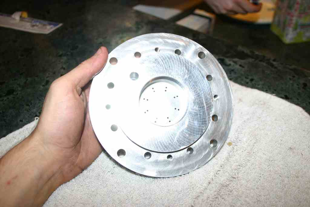
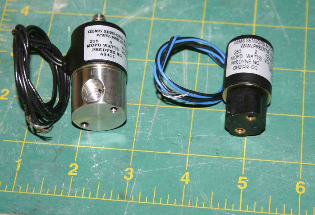
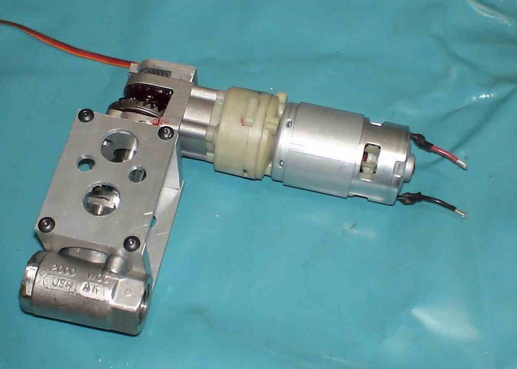
Monday night I worked all evening to make some nice aluminum brackets for our test valve.
I went to bed at 12:30 and got up at 5:45 to keep my appointment at the Gym.
By Tuesday evening I was useless and did no work. I see its going to be a challenge to
both keep the commitment and to throttle the effort so as not to burn out.

Today I finally got the FAA to engage in some discussion and learned a valuable fact.
They are much more open to talk rather than respond to E-Mails as it leaves no record.
I've scheduled a conference call for 9:am EST Thursday (6 am here) so maybe I'll finally make some progress. My agenda for the call is as follows:


Three specific Items I'd like to discuss, and a few more if time and personal permit.


1)Is my concept of having two redundant flight termination systems
that are completely separate from the vehicle operations hardware and software acceptable?

Specifically:
System 1 continuously calculates the instantaneous impact point at 5Hz
and terminates the flight if the IIP hits the predefined defined boundary.

System 2 Is a commercial PCM RC receiver that terminates the flight on command or on loss of signal.


2)What limitations are necessary for staying within the 14.99999 second rule.

Can I carry more than 14.999999 seconds of fuel with a hardware timer that terminates
thrust after 14.999999 seconds of burn time?

Is sensing valve position sufficient to establish burn times?

Is a post burn cool down purge with water and/or inert gas counted against the burn time?

I want to test the vehicle at full gross takeoff weight with the same dynamics as
a fully fueled vehicle. I'd rather not have separate non-sloshing weights as this is an
unrealistic test.


I'd like to set up two temporary metal road plate pads at FAR and


3)What are the requirements for tethered operation?
Rather than do serious worst case mechanical tether analysis can I have the tether carry an electrical circuit, if the
circuit is broken terminate the flight.


Additional items...

Hardware design items:

My intent is to make the safety termination systems separate isolated battery powered
units. The only external connection will be a fiberoptic status output so the units can report battery condition
and self test completion to the outside world. Fiberoptic is chosen as there is no physical way to transmit
electrical transients back into the units that will kill them.

I plan to do full environmental shake and bake qualification on all safety termination systems.
I'd prefer to do this with self constructed temperature chambers and vibration tables,
but If more formal methods are required I'm familiar with the process as I used to run a
"shake and bake" environmental stress screening operation that tested avionics for the Navy.


How would the FAA like to see positional IIP limits input into the system
Some possibilities:
Physically carry the box to the boundaries of the termination area.
Establish a center point by physically transporting the box there and then draw boundaries.
Enter the boundaries from a map or other source of geographic data.
Can the boundaries be simple rectangles?
Convex polygons?


I realize that calculation of Ec is not required for an experimnetal permit, but I expect that one will be done
in any case. Is there any benefit in qualifying sub components in a real world environment and
demonstrating a low probability of failure, showing operational reliability by test?

I'm thinking about putting the navigation,stability,control, and safety termination systems on a RC helicopter
and having them fly vehicle competition profile hundreds or even thousands of times.

Any benefit in having a RC plane or helicopter fly the boundaries of the IIP box for visual verification?


From todays phone conversation it is clear that the FAA does not like my choice to
do all my testing at FAR under the 15 second rule. With a limited budget I just can't afford
to do it a Mojave without some external funding. If we get to the point where that becomes necessary maybe we will have enough visible results to attract some funding.

Specific Progress Tuesday and Wedensday
I finished up the PCB design for my helicopter tester.
I hope to fly an RC helicopter with the same telemetry and control as the rocket and
start testing and writing the command and control software. I will see is my tine Trex 400 can lift the equipment otherwise I will need to buy something bigger.

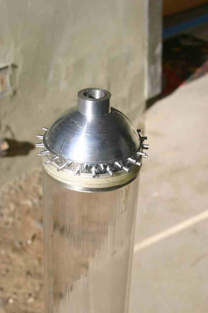
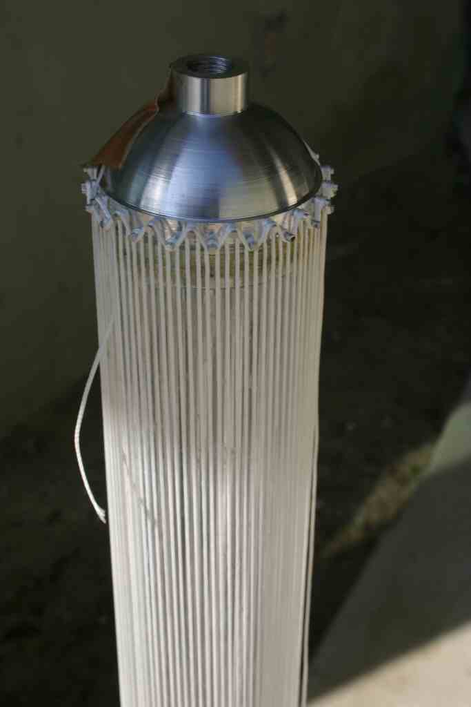
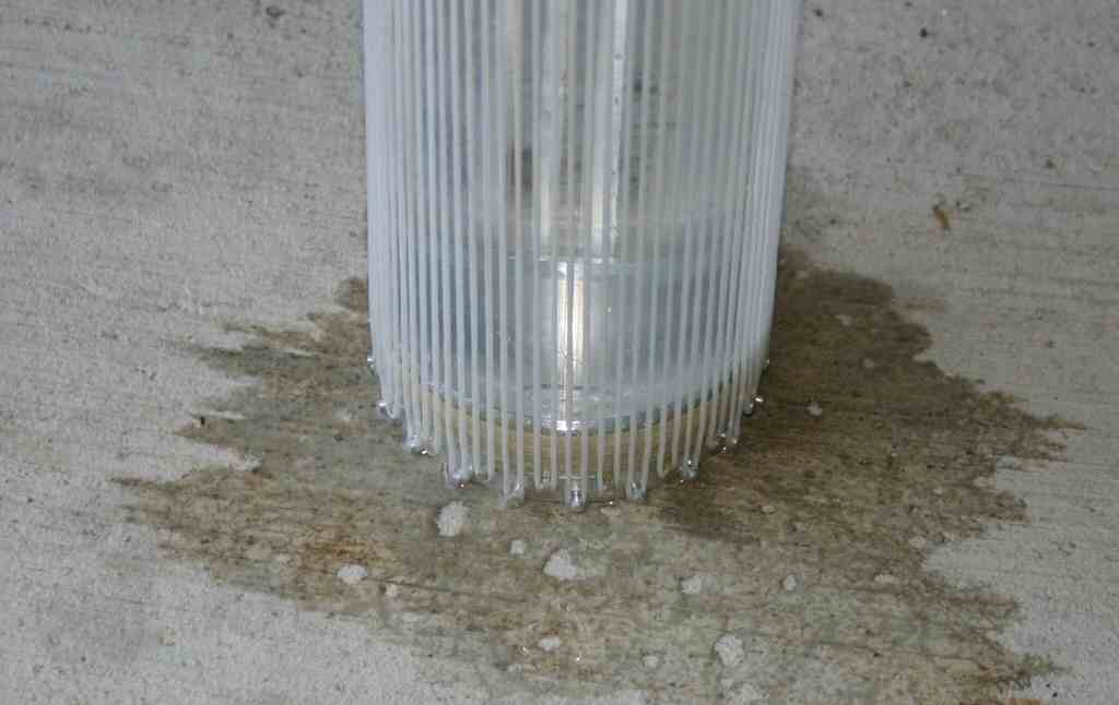
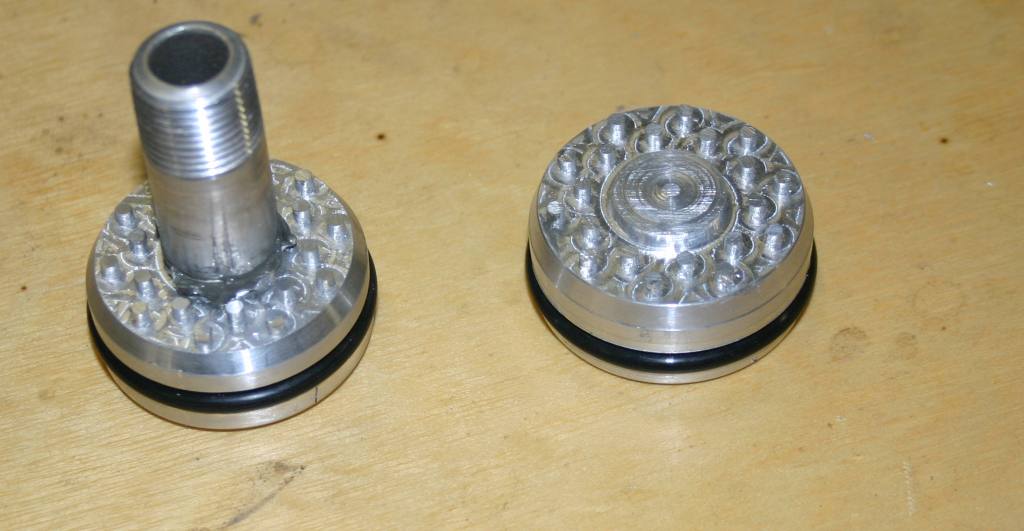
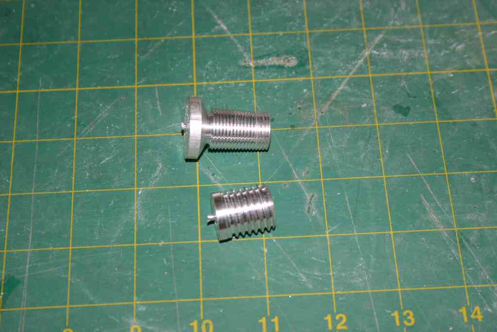
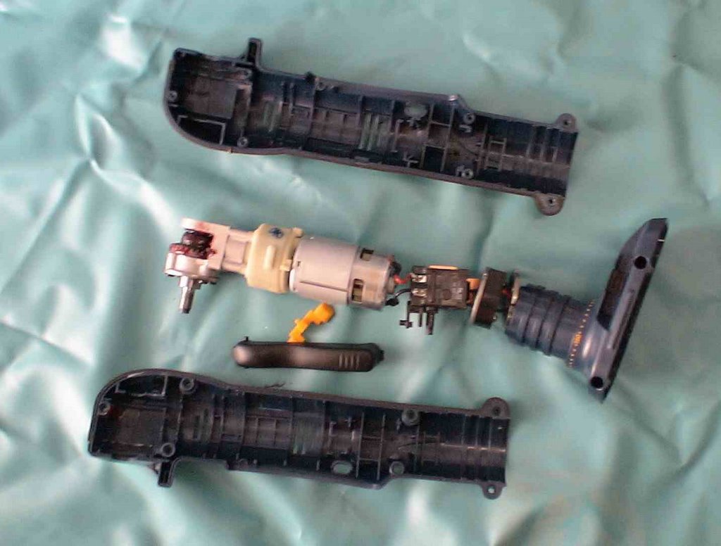
Tonight I hope to finish my first drill driven prototype valve.


Paul


Monday, November 06, 2006

The first big single purpose check.

Today I sent the xprize foundation a 2K check,
my first downpayment on the project I'm on the way to being an
offically registered partcipant.

I'm also starting to make a slight bit of technical progress.
This weekend:
I met with seveal other rocket nuts at the FAR site and discussed designs and ideas
with Charles Pooley and Ken Mason.

I spent sunday finishing my Lathe. I have a 13x40 birmingham manual lathe.
I had the mechanics converted to CNC by Industrial hobbies, they did all the mechanical work and I did all the wiring and electrical. I've had the Lathe for a year and never got around to finishing all the wiring. Last night the lathe cut it's first metal, and all of the CNC parts seem to be working.

Sunday evening my son and I did some work on converting a Ryobi right angle drill driver to a
valve driver. We mounted GMW angle sensors on the end of the spindle and used a Netburner and a Scorpian XL driver to drive the valve. With simple proportional control it overshot
unloaded and did not do well when loaded up. In the next few days we will ad the rest of the PID
constants and see how it works.

Thursday, November 02, 2006

Decisions already made...

On my very first post I posted a list of questions and decisions
that need to decided and answered.
In reality some of the decisions have been made by defualt.

Where can you test a rocket?

All of the significat testing will be done at the FAR site.
What will the AST (government) let you test?
I just don't know yet. All of the significat milestones can be tested under the 15 second non-licensed rules. The 90 and 180 second hovers can be done on a tether.
Do you build things in your shop or hire out to have part made?
I've spent the last two years equiping my shop, so for me this is a no brainer.
I have a converted 13x40CNC lathe and a Tormach PCNC100.

W
hat parts do you buy?
Anything youcan. In reality . Maybe some and some elctronics assemblies, but most of the stuff is built from scratch.

W
hat parts you design and build yourself?
Almost everything.
What fuel do you use?
While I've toyed with hydrogen peroxide, the reality is that the only resonable propellants are something and Lox. for ease of development something is almost certain to be good old moonshine otherwise known as
ethanol..

Whoose techncal advise do you trust?
I trust the guys at flowmetrics.
I trust the written wizdom of John Carmack and the Armadillo team.
I trust the Masten folks.
At some level I'll trust anyone that has actually built a biprop motor and run it.

Do you buy an almost working design form a competitor?
One of the other teams has a nice motor design they are willing to sell me at a resonable price.
the only problem is that its the wrong motor. It's the right size, but its too high of pressure to run with a pressure fed system capable of doing 190 seconds. It's damm tempting, but
not until I try on my own and fail.

Do you have the budget to do this at all?
I hope so, please see the previous post.

The background and the commitment.

I've always had the feeling that the "average" life
was somewhat of a waste. I've always had big dreams.
One of my earlier unfinshed projects can be found
here: Solar Glider
This was an insanely difficult project that consumed 5 years of my life.
As you can see on the web page I have a working design, but I
fell short of my record setting goal.

About the time I last flew the solar splinter I wandered into the
flowmetrics shop (www.flometrics.com) and discovered the SDSU rocket project.
Here were a bunch of inexperienced students building aliquid fuel rocket.
I was impressed, but on closer inspection it did not seem to look that hard.

So for the next two years I provided them electronics when they launched
and spent a lot of time talking to the wizards at flometrics.
I also bought every book on rocket motor propulsion design I could find
and this has been my bedtime reading for the last two years.

By reading, studying and watching others (principally armadillo) I've come to
believe that a normal humans with moderate funding can do significant
rocketry. As that realization slowly sinks in, I've equipped my shop
with what I think is necessary to actually build rockets. CNC lathe, Mill, and good quality welding equipment. As this realization slowly comes to be I also start searching for a worthy
goal.

My inital thought was to do ameateur sputnik. Build a rocket in a garage that can reach orbit. Not with any payload, just a 100 gram tranmitter that circles the globe and
transmitts "Normal mortals can reach space". This is a very hard goal it has significant technical
and significat regulatory issues. I also believe that done as an ameteur project it would take about 1M$. Too hard, too much $ and too lofty.

As I'm in the midst scheming how to do this, I hear about the Nasa/Xprize lunar lander challenge. It looks like the prefect project.
It's hard, but not impossible, the regulatory burden exists, but it is not insurmountable.

So this has become my quest. My guess is that it will take $100K to build a working vehicle that can do the task. I think it will also take another 50 to 100K to prepare for and campaign
the vehicle at the xprize cup. If I live frugally for the next year I can spend this much without
causing any permant financial hardship. the whole family is now on a budget.
I have done things like cancel my dish network subscription, if I'm going to do this I have no time for TV.

Tuesday, October 31, 2006

A week of decisons

"Reasonable people adapt themselves to the world. Unreasonable people attempt to adapt the world to themselves. All progress, therefore, depends on unreasonable people." - George Bernard Shaw.


I'm starting an effort at competing in the
Xprize Cup Lunar Lander Challenge.
It is a hard problem, not because any one part is hard but becuase there are many different parts that need to work together.

The basic technical requirement is that you build a rocket powered vehicle that can hover for 180 seconds. This basic physical fact is goverend by the rocket equation.

DV=ISP*G*ln(Mi/Mf)
DV -- Delta V or change in velocity (DV needs to be > 1800 m/sec)
ISP -- a measuremnt of rocket engine efficency. It is the number of seconds that you can make one pound of thrust with one pound of propellant.
G is acceleration due to gravity. (9.81 m/sec^2)
ln is the natural log.
Mi is the Mass Initial. Or the weight of the vehicle including fuel at the beginning of the burn.
Mf is the Mass Final or the weight of the vehicle at the end of the burn. (the empty weight of the vehicle if you burn till its empty)
You can control some of these, specifically you want Mf or the empty weight of the vehicle to be as low as possible. You want the ISP of the engine to be as high as possible.
You get high ISP by running high rocket chamber pressures (but this makes tanks heavier)
Lots ot technical trade offs.

Beyond the mere technical decisions bussired in the rocket equation there are a host of decisons that are more mundane.

  • Where can you test a rocket?
  • What will the AST (government) let you test.
  • Do you build things in your shop or hire out to have part made.
  • What parts do you buy?
  • What parts do you design and build yourself?
  • What fuel do you use?
  • Whoose rocket design advice do you trust?
  • Do you buy an almost working design from a potential competitor?
  • Do you have the budget to be able to do this at all?
All of these questions need answers and a plan for resolution.
Drawing a rocket design on a CAD system is one thing. Getting it built with real valves and a real electronics is another.

In the comming days I will talk about all of these issues.