Saturday, April 14, 2007

106 second burn Good Motor/Bad Motor


Good Motor:
We ran the 250lb regen motor again today. We ran from full tanks to depletion at full throttle, between 105 and 106 seconds. It lit a bit hard, and it had a bad fuel leak, but otherwise it was an almost perfect run. The video up on youtube .

Bad Motor:
On the way home going up the hill on hwy 14 we blew a head gasket in the truck. It took 6 quarts of oil and 2 gallons of water to get home.

Data:
The data is below. the Load cell gave me qualitatively reasonable data, but the calibration can't be right, with the measured chamber pressure and throat size, I'd see more thrust with no expansion cone at all.... alas there is something I don't understand about the load cell calibration.

Saturday, April 07, 2007

Working on paper work.

Its about 195 days till XPC, so I need to get my AST application in a
sufficiently complete state to start the clock running. I've been working diligently on that. (Its up to about 50 pages and I still have at least one hard section still to develop.) I will publish what I submit and any official correspondence from the FAA here. I will not be publishing the rough drafts and the E-mail back and forth as I don't want to inhibit the communication.

I spent this evening working on a solid copper throat and closure assembly and I should be ready to test again on Sunday. It will be quite a treat to be ready for a Friday outing to test on Sunday!
I might even get some sleep before driving to the desert next weekend.

As anyone who knows me personally knows, I'm not much for sartorial splendor, I do have a never ending collection of tee shirts with thoughtful sayings on them... Like:
Top 10 reasons to procrastinate
1.
(The rest of the shirt is blank)

Given that I think its time I had some Unreasonable Rocket Tee shirts made.
I'll probably do this through Cafe press so if anyone is interested say so in comments and I'll post the design link.

Saturday, March 31, 2007

Testing 3/31/07


Saturday we fired the 250 Lb motor with a new all copper pintile injector. The top end of the motor and the chamber wall worked fine. The Throat/end closure leaked and we melted the bottom end of the motor. It ran for 24 seconds, but the video camera died 20 seconds into the firing. The video is here.

After looking at the data, the chamber pressure started declining almost immediately, so I think the throat was coming apart as soon as we started. We still did not get any load cell data, the load cell worked in the shop, but not when the rocket was running. We have gotten this result twice. The Fuel feed pressure was also very noisy. In the chart below the Tank pressure sensors measure the tank pressure and the feed measures the pressure at the input to the motor after the throttle valves. At the end of the run the Lox tank and feed pressure drops quickly as we vent the tank, but the fuel pressure does not seem to change much. This is because we vent the fuel tank utalage into the motor for purge.

We will make a solid copper throat/chamber assembly and either test next weekend or the following week. It will depend on if I can find a 1st class Pyro op for this coming Saturday.
(It looks unlikely).

Today I started seriously looking at the paperwork necessary for my AST license. It seem like an appropriate day to start ;-) I wrote the beginnings of a hazard analysis and started looking at the procedures and verification processes necessary. Toward that end I also made a slightly more accurate rendering of the vehicle.

Sunday, March 18, 2007

Good Test Results...


The testing went well on Saturday.
We fired 1/4 of a vehicle. We had some software sequence problems that caused it to start roughly but we ran it for 16 seconds with no burn through or other damage.
The Video is here: Video

Sunday we disassembled the motor and analyzed the data. There is good news/bad news.
Good news, the regen motor shows no signs of melting. The bad news is we looked at the data and the presurization problem was more severe than we thought. We never got up to operating pressure. The operating pressure is supposed to be 80 to 250PSI we ran it from 40 to 120 during the test. So we did not run it anywhere near full throttle. This is actually useful data as it shows the engine is stable at low feed pressures, all the way down to 50 PSI. We got no load cell data.


We also fired the 650 Lb Ablative we tried to fire a few weeks ago.
That video is here

Friday, March 16, 2007

We have been busy...

Its 11:33PM and we just finished packing the truck.
Saturday we go out to the test site and test 3 things.

1)The 650LBF motor that we tried to fire last time.

2)A 250Lbf Motor in exactly the configuration we want for the NG-LLC.
This includes flight weight tanks and a torch igniter.

3)My Compressed Air stability software development vehicle.
(See:Here)

The hardware is all 100% ready, both items #2, and #3 need a little software tweaking.
So rather than stay up all night, I'm going to get some sleep and work on it at the site. I may spend Saturday night and Test on Sunday as well.

I'll post video, results and news Sunday or Monday evening. I'm going to Space Access in Pheonix next weekend so if any regular readers are going make sure to say say hi.

Friday, March 02, 2007

Our first Mach diamonds.

Tonight I tested my igniter. It fired correctly on the first attempt.
I did not get chamber pressure so I need to figure that out before I fire it again.
In any case we made our first Mach diamonds.

Enjoy the video...(You tube)
Larger Version on my server.

Wednesday, February 28, 2007

Injector Version 2 flow tests


Based on my previous testing and some advice I received on Arocket I built a new injector.
Its got a smaller pintile and a tapered out area behind the annular gap. the annular gap is only 0.050 deep. the new pintile is only 0.400" across. I flow tested it tonight and the Fuel came out perfectly within 1.5 % of where I wanted. Well within my experimental error! The oxidizer is about 10% low (Meaning I'll need to run my pressure 20% high) Its good enough to test as is. The visual quality of the combined spray cone is very good. I took a fast flash picture of the result its on the left.

I also took a picture of just the fuel orfice


I also tried to take a picture of just the lox spray and got everything in the entire shop wet. Sorry for the bad quality, but after wiping the water off of my Lathe and Mill I was not about to try to take the picture again.

Thursday or Friday I'll try to braze the igniter mount on the the assembly and I'll have a new motor by the end of the week end!

Monday, February 26, 2007

How I got started...

I realized that normal mortals could do liquid rocketry after spending some time with the SDSU rocket team. They have also started a blog, only one post so far.

After watching them build and fly stuff and discovering the Armadillo blog I was hooked.

Update on the week end:
  • Bob welded up two tanks and was almost finished with the third. When the tanks are ready we will have them heat treated and test one to failure.
  • My son went into production mode working on making a batch of 12 of the tonegowa servo valves.
  • I worked on designing and fabricating a new pintile injector based on our flow tests and some feedback I received on Arocket.

Wednesday, February 21, 2007

Some Hardware.


Here is a picture of my Pintile injector.
To give you an idea of scale the tip sticking up in the middle is 0.675 inches across. The small holes are 0.029" I don't have a water proof digital camera so I was unable to get pictures of the injector flowing.


I went to harbor frieght and bought a small sandblasting unit to use for pressurized flow testing. It has a large pressure tight opening on top to rapidly refill with water. It makes a heck of a squirt gun. Using that I flow tested both my lox and fuel flows for my injector. (I tested using water and adjusted the numbers for density) The fuel flow was about 35% low, and the lox flow was about 11% low. The 11% is close, but the 35% is off more than I would have expected. I'll try opening up the annular gap a tiny bit in next few days. It will be very hard to get it re centered. I'll probably end up making another one in the next few days .


Lastly here is a not quite ready to be fired picture of my igniter. The Aluminum box it's leaning on is the electronics for driving the shielded sparkplug.

Tuesday, February 20, 2007

Quick clarification


Carl asked what keeps the fuel plate from moving back and collapsing into the pintile. The cut away view did not show the arms very well, but this view with the pintile turned tranparent does. the three arms are a solid part of the fuel orfice plate. They also align the two plates. The outer aluminum casing is turned off in this view.

Monday, February 19, 2007

A New chamber design

I put together a short outline of my vehicle and the safety systems to present to the faa/ast when I was in DC. There are some typos, and a couple of things missing, but its probably worth publishing. astpresnt.pdf.

I have a bunch of new hardware that I will post pictures of in the next few days. I've designed a 250 lb thrust chamber. Its a copper tube with an outer aluminum shell. I've designed the pintile injector and and I built one this weekend. The hard part for a motor this small is keeping the annular alignment between the pintile and the fuel plate the gap is nominally 0.0062" all around. This seems insanely small,(The 25 #69 lox holes in the pintile aren't exactly large) but I did the calculations a bunch of times and it seems to be correct. I machined an alignment step on the pintile and a corresponding recess in the plate that forms the annulus. Goal was to hold the annulus size to +/0.0005" and I think I got it. That is the limit of my measuring equipment.
The alignment recess and step are close enough that if you heat the the plate to slightly warm and cool the pintile to slightly cool they slide together. At the same temperatures they are a tight press fit.

The O-rings I had on hand were not correct to seal in my injector test fixture so I did not get the satisfaction of seeing the injector work. (the o-ring sealed enough for my to try it and get all wet... again.) In the next two days I will be flow testing the injector and I'll post pictures of the hardware.


On the left is a split rendering of the chamber design. To give an idea of scale the inner copper tube has an ID 0f 2 inches. I still have not decided if the throat will be copper or Graphite.
I will try both. The chamber needs to throttle from 80 lbs to 250 lbs. so I set this up to be 50 to 150 % of nominal. Thus the chamber is nominally laid out for 166 lbs of thrust at 166 psi expanding to 12.5 PSI. (the ambient pressure at Las Cruces.) Theoretical ISP at this low pressure is 216 frozen, I'm hoping to realize 180+. The pintile orifices are designed for 32 PSI of pressure drop at the desired flow rate. The orfice sizes were calculated with a discharge coefficient of 1.5. We will see how close I got when I do the flow testing this week. I'll gladly post my notes and spread sheets for all of this, alas I fear they probably won't make any sense to anyone but myself.

I resurrected the lrd (liquid chamber design program ) from the rocketworkbench. I modified it with two additional parameters. water_percent to allow you to add water to your fuel/oxidizer and exit_pressure to set an exit pressure other than 14.7 psi. The program executable is here and an example input is here. If anyone wants the modified source code I'll send you the microsoft visual C 6.0 project with all the files in it. (this also builds cpropep, but the cpropep I built seems to go bboom when I try to run it. I haven't taken the time to figure out why. In the end it turned out easier to use the output from cpropep and a spread sheet.

Sunday, February 11, 2007

Saturdays Testing(updated II)

From the lunar lander project perspective everything on Saturday went perfectly. The systems all worked as designed, we had no frozen vales, instrumentation or computer problems all of that was flawless.

The real story is we were testing an older engine design that used a pyrotechnic igniter and we and that failed to get it lit. So some time in the next 24 hours I'll post a very boring video of Lox and alcohol coming out of a motor in unburned form.

If we had more Lox we would have tested again, but we were using the left over Lox that had been delivered for a different project. By the time they were done there was less left than expected. My son was very disappointed we did a lot of work and got no flames, booms or other intersting pyrotechnics. I was happy with the result because the components of the test that apply to the XPC project all worked flawlessly.

Here is the test video, kind of boring, I've also uploaded an unrelated video of other rocket things...

Saturday, February 10, 2007

Its 2am the thrill is gone....

A number of knowledgeable people keep telling me to start fireing a Motor, any Motor to get experience with liquid rocket motors. This summer my son and his friend Jason built a test stand and rocket motor. I built the Injector Plate for it. Due to valve issues it was never run.
We have put new valves on it and its ready to test. Since our test site has a lot going on this weekend and we decided this would be the weekend. Alas everything takes longer than expected.
One minor example... I'm a founder at Netburner, so the electronics that runs the test stand is all based on Netburner modules. Well the sample code that I brought home this evening to use uses a relatively new NetBurner feature so the code release that is running on my laptop does not support it. So step one is download a large file and reinstall tools... It went down hill from there,I think were finally ready to go, but the garage looks like there was a tool explosion...

It's 2am and I get up in 4 hours, as the song says its 2am and the thrill is gone....

Sunday, February 04, 2007

Quick Update

A quick update before I catch a plane.
  • Tanks: I found a place where I can order thicker T0 aluminum, the aluminum for thicker end caps will be here on Feb 7th. I also found a local place to do post weld heat treating, this should get me to my goal of 500 PSI with the aluminum tanks.
  • Igniter: I fabricated an Igniter using orfice sizes and the basic construction concepts that John has documented on the Armadillo updates. The Igniter, solinoids and ignition system is lighter than the weight allocated on my virtual vehicle. Having something tunr out lighter is always a good thing. I'll test it late next week.
  • Paperwork:I'm flying out to DC to attend the AST commercial space conference, I have a meeting with AST on Monday I'm going to try real hard to learn something and be diplomatic.

Wednesday, January 31, 2007

Why building hardware is hard...

Last night I tested an aluminum tank that made it to within 5PSI of my goal, 500PSI. It burst in the end cap. So I set out early this morning to try and make some sturdier end caps. the ones that failed were 6061 T0 0.080" thick. So I thought I'll try it with 6061-T6 0.080 thick. A tiny bit stronger. (Its what I had on hand) So I got up at 5:30 am and made an end cap, or tried... The -T6 is a lot stronger and in trying to form the end caps the 1/4" grade 8 bolts holding the fixture together failed in mass at about 800 PSI. not much of a dome in the T6 at 800 PSI. So at lunch today I went by Marshals hardware and bought a bunch of grade 8 3/8" bolts. When I got home from work this evening I started drilling out the steel fixture to take the 3/8" bolts. I started with the 1/2" "Oh my god" strong hand drill, it jammed in the third hole and snap ed off in the fixture. (I'm getting better at this while I was at the hardware store at lunch I bought two extra drills of the proper size.) So I extract the broken bit and move to the drill press. The drill press is not a big one and it's marginal for drilling 3/8" holes in 1" of steel. I finally finish the fixture, redrill the partially formed T6 plate and reassemble all 36 bolts.
Then out to the hydro pump and start pumping at 250 PSI the o-ring fails. I disassemble the fixture and discover I'd pinched the o-ring on assembly. When I disassemble the fixture I get soping wet as the fixture traps just enough water to surprise you and make all the neighbors still brave enough to come vist think I have an incontinence problem. So dig in the o-ring box and discover that the extra fixture o-ring is not in the o-ring box...... So I figure that I'll try the old o-ring properly assembled. So I set the oring in the grove correctly, careful not to pinch it and reassemble. Each assemble /disassemble step requires about 15 min as there are 36 bolts and the fixture holes are deliberately snug. Reassemble and pump up to about 1000 PSI when the fixture assembly makes a lond bang and starts leaking water. So Back inside and disassemble only to discover that the T6 failed at the edge and failed to make a dome. So I have to use T0, alas I need thicker than 0.080 which is the thickest T0 I can easily find from aircraft spruce. My favorite metal supplier IMS does not sell any T0 aluminum. I started the day with a plan and a fantasy about making two new end caps and bringing them to Bob to weld this evening. At the end of the day I not only have not made any progress, but I've also discovered that my plan of attack is no longer workable. 18 hour day zero forward progress... building hardware is hard.

Tuesday, January 30, 2007

Aluminum Tank Test.

Carl at FloMetrics recommended a local gentleman named Bob to help us with some aluminum welding. Tonight my son went to his shop and held things while Bob welded up an aluminum tank with our hydro formed end caps. The quality of the work was very good, and we tested the tank this evening.

The Tank details...
  • Predicted Tank weight 5.6 Kg
  • Actual tank weight (The end caps ar a bit less deep) 5.25Kg
  • Predicted burst pressure: 558 PSI.
  • Actual tank burst 495 PSI. (End cap was too thin from forming.)
  • Calculated Tank volume disreguarding 1/2 the end cap volume to account for shallower than spherical end caps: 51.3 liters
  • MR 10.78
A picture of the burst tank end:


I'm very happy with this test. This is the exact tank design that is in my vehicle model
Bob was going to weld up a pair of tanks, but I think I'm going to have him hold off on the 2nd tank until I can hydro form some heavier endcaps of slightly thicker material. So we now have working valves, and a workable tank. Next up an ignitor, thrust chamber and paperwork.

Saturday, January 27, 2007

Normal Metal Tanks...

If I can't get my spectra tanks to work, I need a backup plan, toward that end we are fabricating two possible tanks. A Tank made out of aluminum thinwall tubing and hydro formed end caps. I spent Saturday fabricating end caps that will be welded to the aluminum thinwall tubing.
Here is a cap being formed in the forming fixture:


After pumping about 600 PSI water into the fixture the pressure is releived and the endcap is removed and put on the mill, indicated for center and then machined out of the blank.


The result is :


My son welded up the stainless hemispheres, and we tested these...


The first test sprang a leak at 450PSI in the weld, we patched that and it sprang a leak at 590 PSI, we patched that and it sprang two leaks at 710 PSI. All leaks so far have been in the weld area. The theoretical burst for this tank should be between 800 and 1300 PSI depending on if you give any stress credit for stretching the tank and work hardening it. So 710 is close to this value. The MR of this 18" tank is about 7.6 . The aluminum tanks we will weld up Sunday have a theoretical burst of 550 and an MR of 9.6.

Thursday, January 25, 2007

A plea for paperwork help.

I have negative amounts of tact and diplomacy when dealing with bureaucracy. If I think something is Bu****it I say so. I'm coming to realize that unless I get someone other than me to deal with the AST I'm not going to be successful. So what I'm looking for someone to do the following:
  1. Help me wade through the experimental permit process.
  2. Help me figure out exactly what technical supporting docs I need to prepare.
  3. Present this to the FAA/AST in my behalf.
If anyone is interested in working on this as a paid consultant please contact me. If I've already talked to you there is no need to respond again.

To contact me send E-Mail, you will have to answer to my SPAM filter.


Sunday, January 21, 2007

48" long wound FTC test

I tested the 48" wound florescent tube cover tank to failure this morning. At around 1500 PSI it started weeping around the o-ring. At between 1900 and 2000 PSI the pins on the aluminum end cap failed. All the pins were sheared off, and none of the spectra was even torn. I'll post detailed pictures later.
(The tank was 337 gms and held 1.65 Liters of water. for a MR >5 at 1500 PSI)

Saturday, January 20, 2007

I got up this morning and hydro tested my 3" wound tank. It failed at 200 PSI in dramatic fashion. It shattered into a bunch of little pieces.
As you can see in the picture on the left the PTEG tube has lots of little cracks. After this failure I suspected that maybe something was wrong with my initial small scale test with the Florescent light tube cover. So I retested that, again the fitting leaked and again it held to 1500 PSI. So I suspect that the PETG tube and the FTC tube were made of different stuff. I've decided to disassemble the old small FTC tube, fix the fitting leak and try again. I'm letting the oring overwrap reenforcement dry and when that is done I'll wind another tank and test it on Sunday.

Just in case my spectra tanks don't work out I'm also working on lightweight aluminum tanks. I built a hydroforming fixture out of a large chunk of 12" diameter Aluminum and a 12" diameter steel cover plate.


The frist try at using this fixture was ok, but not great. the only Aluminum I had was 6061-T651 so it was hard and did not yeild well, I've ordered som 6061-T0 and we will see how that works. The resulting end cap from the -T6 was usable, but shallower than I would like. It failed around the edge of the fixture, so my guess is that I need to radius that part of the fixture a bit more. I send E-Mail to two metal spinning companies asking for quotes on having them make 8" hemispheres and I've gotten no answer.

Friday, January 19, 2007

Thanks to all for the help.

I started this blog because I'd enjoyed reading about other projects from the engineering perspective. I'd hoped that others would enjoy reading this. What I did not expect is that I would receive help from my blog readers. The examples of this are numerous. I've had two different people run PET LN2 experiments and e-mail me their results. John Carmack of Armadillo has made numerous helpful comments. Just this week my son was working on my wound tank o-ring seal and went to visit "Real Seal" looking for Lox compatible seals.
My son discovered that Kevin at Real Seal is a reader of my blog. My son has been back once more to get a slightly different size and the people at "Real Seal" have been very helpful. I insisted that he pay them for the O-rings he picked up, but based on what McMaster Carr charges me for O-rings I suspect that the rings he got from Real Seal were sold to us at below market prices.

Using these new O-rings we put together another 3" wound tank. We finished it tonight and its holding water. I glued the end of the spectra down and I have to let that glue dry. We will pressure test the assembly on Saturday. I'll have pictures of the result as well as some pictures of our hydroforming fixture for making 8" aluminum end caps.

Some people may wonder why I'm spending all this effort on tanks. It's not very sexy and making hot flamey shock diamonds is much more showy, but the tank mass also appears in the rocket equation and if I can reduce the dry mass of my tanks by 50% its the same as adding 30 seconds of ISP to my rocket engine.

Best Wishes for Spacex

Some time in the next week it looks like SpaceX will try a static fire then a launch. I hope the mission is a 100% success! We need more successful private space ventures.
Update SpaceX will not fly till mid February.... something wrong with the 2nd stage TVC actuator.

Monday, January 15, 2007

A Widget for the Xprize Cup fans...

I was working on schedules and thought I need a reminder of how long I have left. So I wrote a simple little MFC application that counts down till the xprize cup.


If you want a copy of the application it is here. Beware this is zip with an exe file in it. In general it is a very bad idea to download an unknown EXE file from someone you do not know and run it. I would recommend that you virus scan this before using it. For those that want the source code it is here....

Thursday, January 11, 2007

Tonegowa Servo Success...

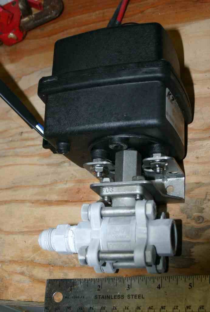
Tonight I tested a valve based on the tonegawa PS-050 servo. It's 890 grams and seems perfect. I'm posting a video of the 350 PSI LN2 test and it works really well. The video is at here. The mechanical set up for the tested valve had a few issues. So my son built a second valve based on the Tonegawa it is 781 grams and works just as well. I think we have our first flight weight bit of actual XPC hardware.

Sunday, January 07, 2007

Leaking O-rings explained

I spent all day Saturday working on the o-ring seal problem with my tanks.
I'm 90% sure I know what the problem is.
After trying everything under the sun with respect to o-rings sizes grove depths etc...

I did an experiment, I built a tapered hollow aluminum plug and an aluminum ring that goes on the outside. I heated the PETG tubes and slid them over this tapered plug. I then filled the tube and a plug with Ln2 and let them cool. (To make them shrink)

I boiled the ring that goes over the outside in water. (To make it expand)

I then drove the heated ring over the outside of the assembly.

This explanation sounds simple, but I machined the plug and ring diameter 10 or 15 times to get all the tolerances right.

I then let every thing return to room temperature.

I filled it with water and it still leaked.

Examining the plastic tubes under a magnifying glass I see that the extruded tubes have fine ridges or groves and these seem to make little capillary tubes that lets water seep through.

I'm now once again looking for clear, smooth plastic tubes.

Friday, January 05, 2007

3 working valves.


Tonight I LN2 tested three different valves.
ALL three worked to turn 350PSI LN2 on and off, even after LN2 soaking to get cold.

The first valve is a Home made valve made valve with a banebot 36mm 256:1 gear motor.
This valve is 900 gms.


The second valve I tested is the Drill motor valve as previously described on this blog. 1.2Kg


The Third valve I tested is KZCO actuated valve like Armadillo is using. It is a bit more than 2Kg.

Sunday, December 31, 2006

Leaky O-rings...


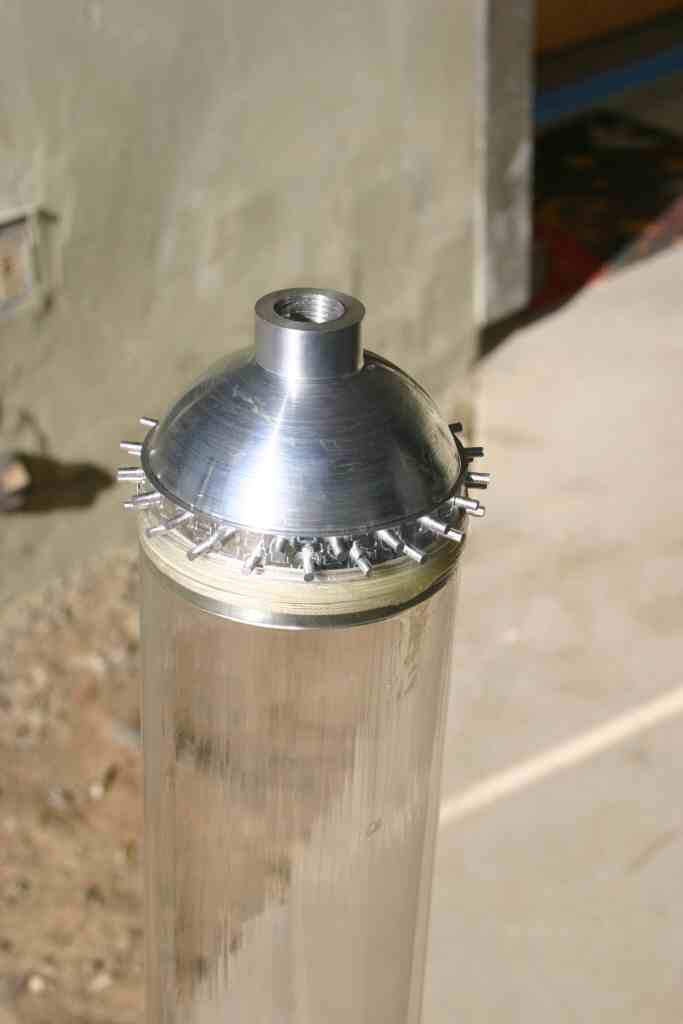
In my first little tank I used soft rubber o-rings. These will not work for LOX. So I've spent the last two days trying to get PTFE or FEP encapsulated o-rings to not leak. I've been trying to build a 3" tank to test my PET tank ideas. The picture on the left is the top end of the tank after the first winding step to reinforce the area around the o-ring before starting to wind the longitudinal fibers.
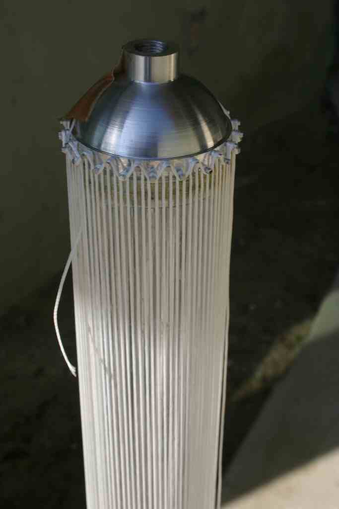
The next picture is the tank with the longitudinal windings in place, about to be filled with water before doing the radial winding. I did not get past this point because....

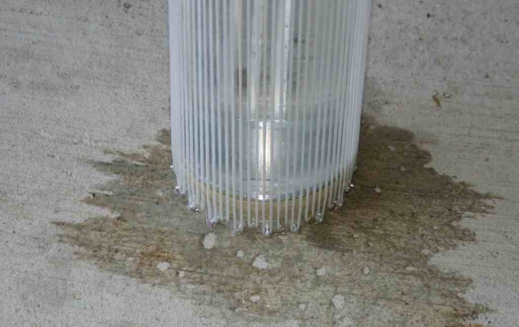
The third picture shows water leaking around the seal.
Having a light high pressure LOX tank would greatly simplify some of the project, but it's not worth spending a whole lot more time on. I'm going to order some more o-rings from McMaster carr and try one more time , but if I can't build light LOX tanks I'll just use aluminum irrigation pipe and work to get something flying. I have to keep reminding myself that perfect is the enemy of good enough.

Monday, December 25, 2006

Gone for a few days...

I spent the days before Christmas working on a 3" version of my Tank. I machined two spherical end caps and they looked good up to the point I CNCed the lacing posts . I ruined one of the caps and need to make another.

I did to some ln2 tests with the end cap. With the PET tube filled with Ln2 it does not leak or break, and the PETG still seems flexible.

You won't here from me much for the rest of the week as this is my 20th wedding anniversary and we are going away for a few days.

Monday, December 18, 2006

An Update...

Site Prep:
Last Wedensday I went out to the FAR site to help pour the big test stand. 5 People poured 145,000 lbs of concrete in about 6 hours. It looks like it all went well. Many thnaks to my wife who came out and helped finish the concrete. Jerry Irvine took lots of pictures if I get a picture of her with the trowel in hand I'll post it. This project would not be possible without her support.

Valves:
I ordered some more three piece valves from McMastercarr I'm going to make up the following valves and test them: Drill Motor Drive, Industrial Servo Drive, and BaneBot motor drive. I will LN2 test these and the KZCO valve this weekend! I have the week after Christmas off so I have high hopes of getting lots done.

Tanks:
I was told that the florescent light tubes are Polycarbonate, not PET, so I ordered some 3"x36" PETG tubes from Uline packaging. They assured me that the tubes are PETG, alas they look just like the florescent tube covers just bigger. If anyone has a bullet proof way to identify PET please let me know. PET Soda bottles shrink when heated, these tubes do not seem to do so.
In any case I'm making new spherical tank end caps for the 3" tubes. Its amazing how much
aluminum chips can come from a 3" long 3" diameter block of aluminum....

Testing..
My last tank leaked at the fittings. So I spent Most of the day Sunday making NPTF pipe threads on the lathe and testing them to see if they are pressure tight. Today my new hand pumped hydrostatic tester arrived from McMaster Carr. (Thanks Xcor for the tip)
I hooked it up bled most of the air out of my fitting and tested my fitting to 3000 PSI the good news it held... The bad news in my hurry to test my handy work I did not bleed the air out of the hose and it did not dawn on me that the hydro tester has no bleed valve, so now its sitting at 2700 PSI and I'm afraid to crack the fittings. I'll let it sit for a day and hopefully it will bleed down. When I was working on my instrument pilots license, any time I had a spare moment to think me my flight instructor would ask what are you working on now....the proper answer at all times was the next thing. Making sure that you know what the next thing you are going to do no matter the outcome is good advice for all aspects of life.

Monday, December 11, 2006

Back to Valves

My son spent the better part of Sunday machining an adapter to adapt an astroflight brush less motor with 19:1 gearbox to one of the right angle drill mechanics. I tested it this evening and its very disappointing. The sensorless brushless motor does not start well under load. Maston had speed problems with their brushless valve drivers, and I suspect it was because the driver uses back emf to sense the position of the rotor and startup must be slow to get synced up.

I ordered a couple of KZCO valves like the Armadillo team uses and the arrived today. With the top case off of the motor and the cable removed it weighs 1528 grams. With a bit of careful trimming I think I could get it to 1300 grams. My ready to go valve assembly weighs about 1100 grams. My valve is faster, lighter cheaper and and more powerful.

I made a video of the valve operating and just uploaded it to you tube.

Sunday, December 10, 2006

Tank pressure test success...

I did not have a small enough threading tool or tap to make the threads in the tank end cap. When I got a pipe tap I broke the tank when twisting it. So I'm doing it all again now that the fittings are threaded.... This give me the opportunity to take more pictures and weigh things....
The end caps:


The end cap weigh 40 gm for the blank end and 61 gm for the end with the fitting and pipe nipple.
The aluminum end caps weigh more than the whole rest of the tank. While the origional short tank had a mass ratio of 3.5. An 8 foot version constructed identically would have a MR of 6.7 .
To put this in persepctive, an aluminum sphere with 31000 psi UTS will have a MR of around 6.4. After I threaded the fittings I built a new tank that was about 18 inches long to try and pressure test. I took it by my friends at FloMetrics and we pressure tested it to 1500 psi. It did not fail at 1500 psi, that was just the limit of the water pump we were using to presurize it. The NPT threads around the pipe nipple leaked, but the tank held at 1500 PSI! Since I had used the pipe nipple as a winding post I could not tighten it to make the leak go away. I've been told that aluminum NPT pipe threads leak badly, but some things you need to learn yourself. If anyone has recommendations on a type of pipe fitting that can be used in aluminum and won't leak please let me know. Next time I get a dewar of LN2 I'm going to hook a pressure transducer to the tank and burst it at low temperature. I'll keep everyone posted.
I may also try fabricating some larger PET tubes and building a 4 or 6" tank.

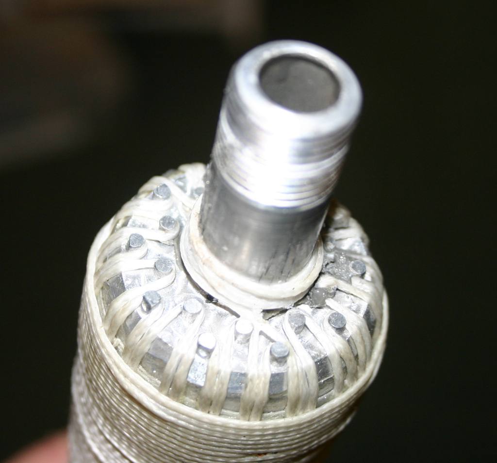
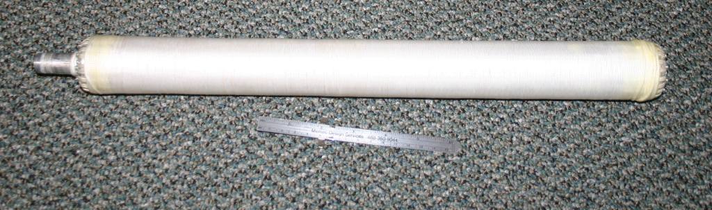
A picture of the whole tank:I did not use any glue on the main part of the tank I only used "gorrilia" glue on the ends to secure the windings.

Saturday, December 09, 2006

A test of pop bottles and kite string.


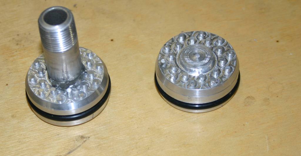
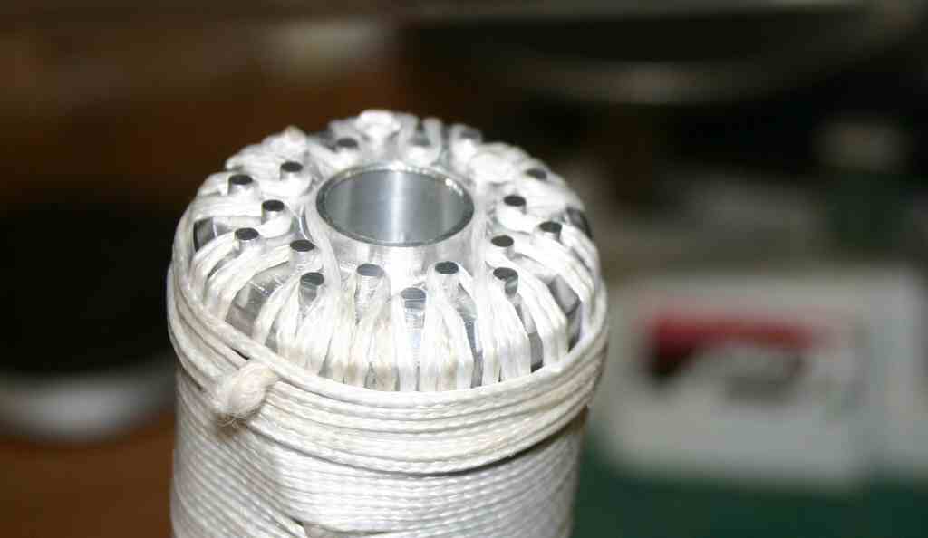
I spent the day fabricating a test tank. I machined some aluminum oring sealed end caps to go on a short length of florescent light tube cover. (Made out of PET or the same thing as a 2 liter soda bottle. )The aluminum end caps were machined with pins on the ends to hold the longitudinal lacing.

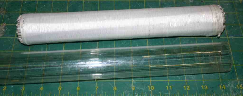
The tank ended up heavy with a MR of 3.5 using water, but its small and has a theoretical bust pressure of several thousand pounds. It was not meant to be a flight weight tank as it is short and should be much stronger than needed. Its more of a test piece to see if I can get anywhere near the predicted performance out of spectra wrapped tanks. I suspect that the failure mode when I pressure test it will be to blow out the o-ring seals.


On the left is a picture of the finished tank with a piece of unwrapped light tube next to it.
If the pressure test goes well, I will Ln2 pressure test to destruction. If both of those go well I'll try fabricating a larger more flight weight tank using the same concepts.


I'd taken some project pictures while working on things before I started blogging....
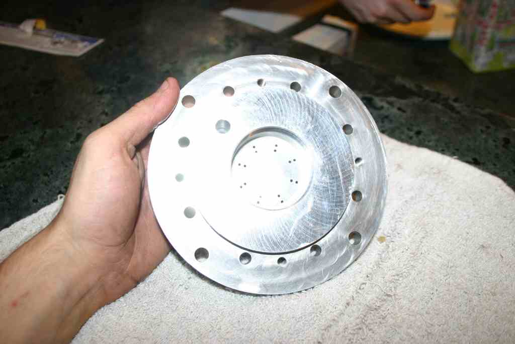
I'll post some of these from time to time...This is a picture of a 600lb Lox ethanol motor injector plate I fabricatedit last summer. We never fired it because we had valve problems and probably won't fire this one until we have more things to test. (Such as an igniter.)


Sunday, December 03, 2006

Another weekend gone...

Saturday I spent the day at the FAR//MTA site. I was working on some forms for another storage container at FAR. I'm on my knees digging in the desert sand with my hands to make room for the form , and I realized that building rockets this way was a lot like grilling a hamburger where the first step was to plant the grass to feed the cow....

The RRS was having its Christmas party the same day and the RRS/MTA had a few interesting things going on. I'm not all that taken with the unguided HPR soldis and hybrids they remind me of artillery. I did find the large 4000 lb thrust Lox methanol that was test fired interesting.
As Keven said "That was a manly sound" If you have ever heard a liquid rocket fired it is a sound that you will never forget. No recording I've ever heard did it justice.

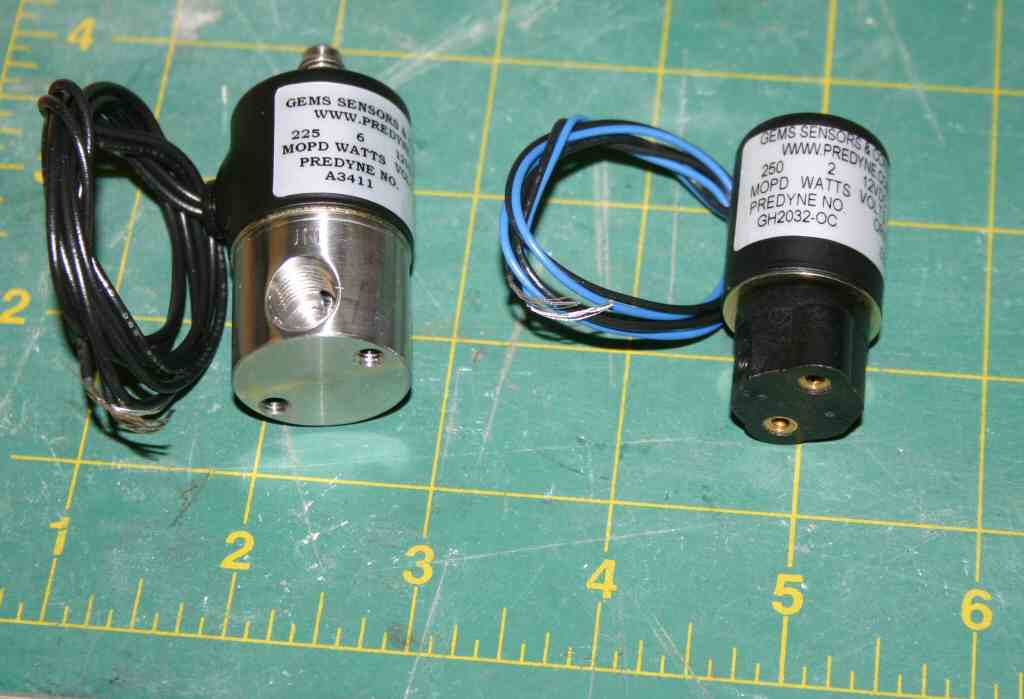
A number of bits and pieces arrived this week. I got the solenoid valves I ordered from Predyne I got 6 valves in two different sizes these will be used for building an igniter and doing purges. Unlike Snaptite, predyne will sell in small quantities to normal people. So I can get more valves when I need them.


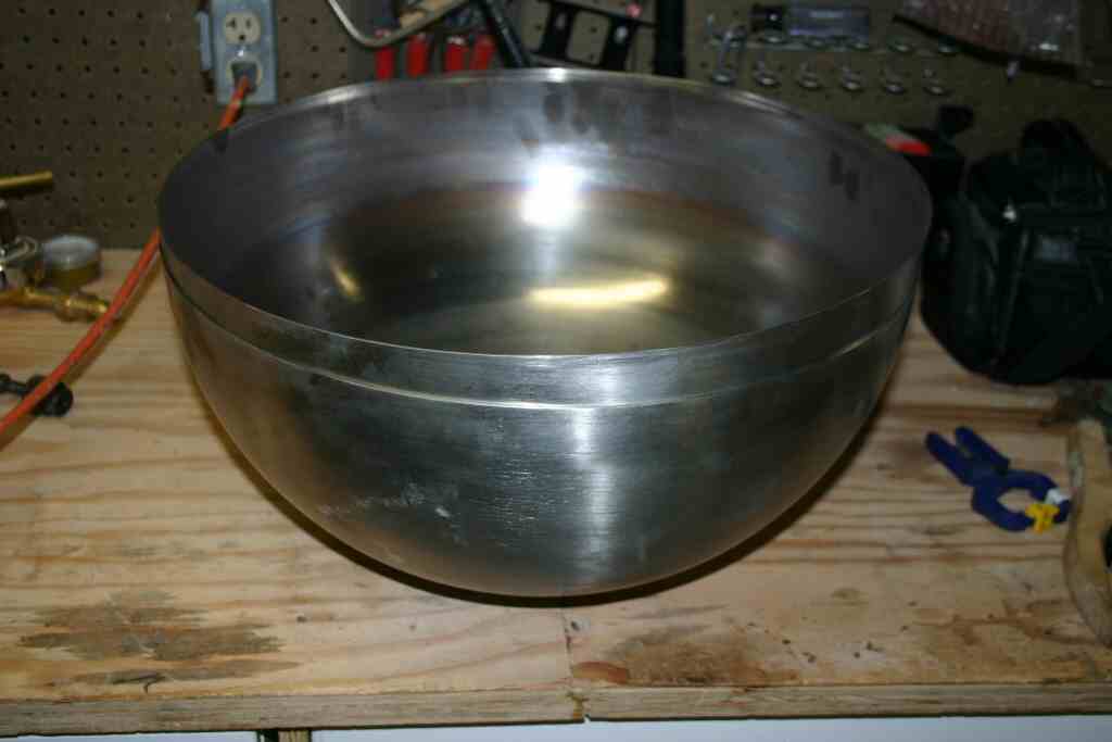
I also received my stainless steel Hemispheres from AMS industries to build some spherical stainless tanks.These are 18" diameter 316 Stainless. the thinist point is about 0.064 thick.
My son has finals next week, when that is done He will weld them up and we will hydro test them. I plan to use the same strap technique that Armadillo used to align them. (Thanks John for being so open and public!)


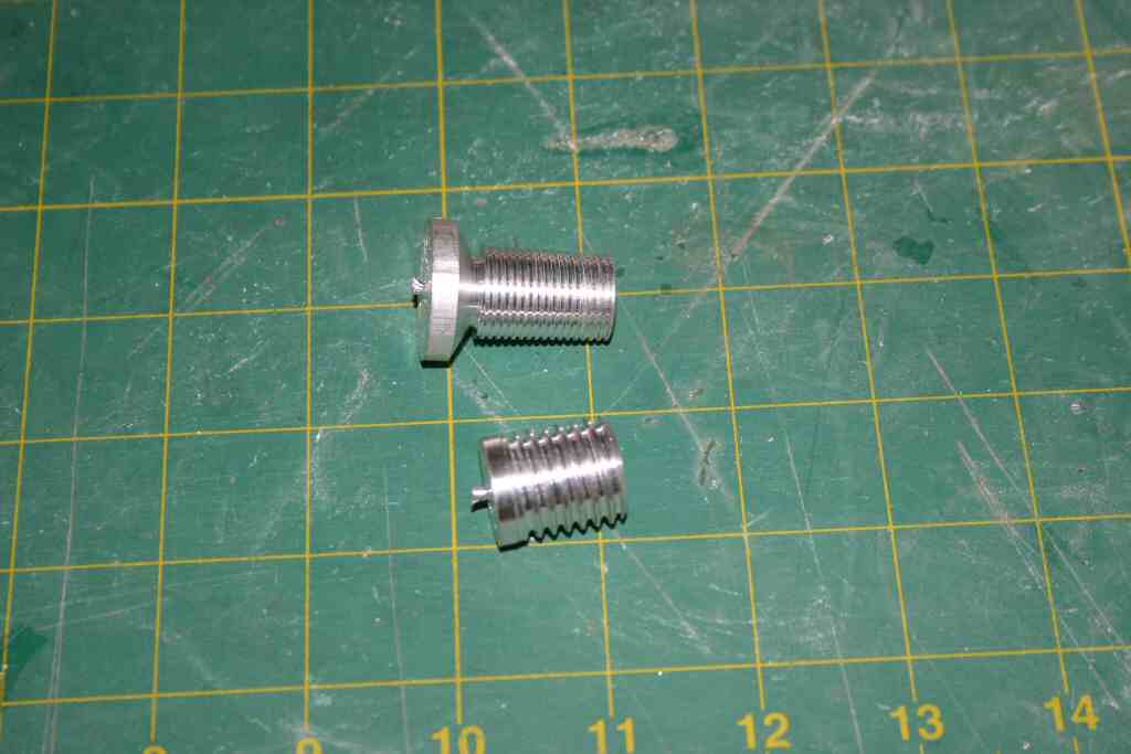
Lastly I spent Sunday working on my personal skills. As I indicated in my post on the CNC myth it takes skills to build things using CNC machines. I've spent about 18 months working with small CNC mills, but I have almost no time using a CNC lathe. So I spent the day with some scarp aluminum bar stock turning things to diameters and then making threads.
the straight threads took my 5 tries to get right... After I had all the bugs in that worked out
I made some tapered NPT pipe threads. I got that right on the first try. It does not look like much but the results:

Straight thread on the bottom and tapered pipe thread on the top.
The pipe thread is longer than it needs to be, but the taper is correct.


Wednesday, November 29, 2006

Shop space...

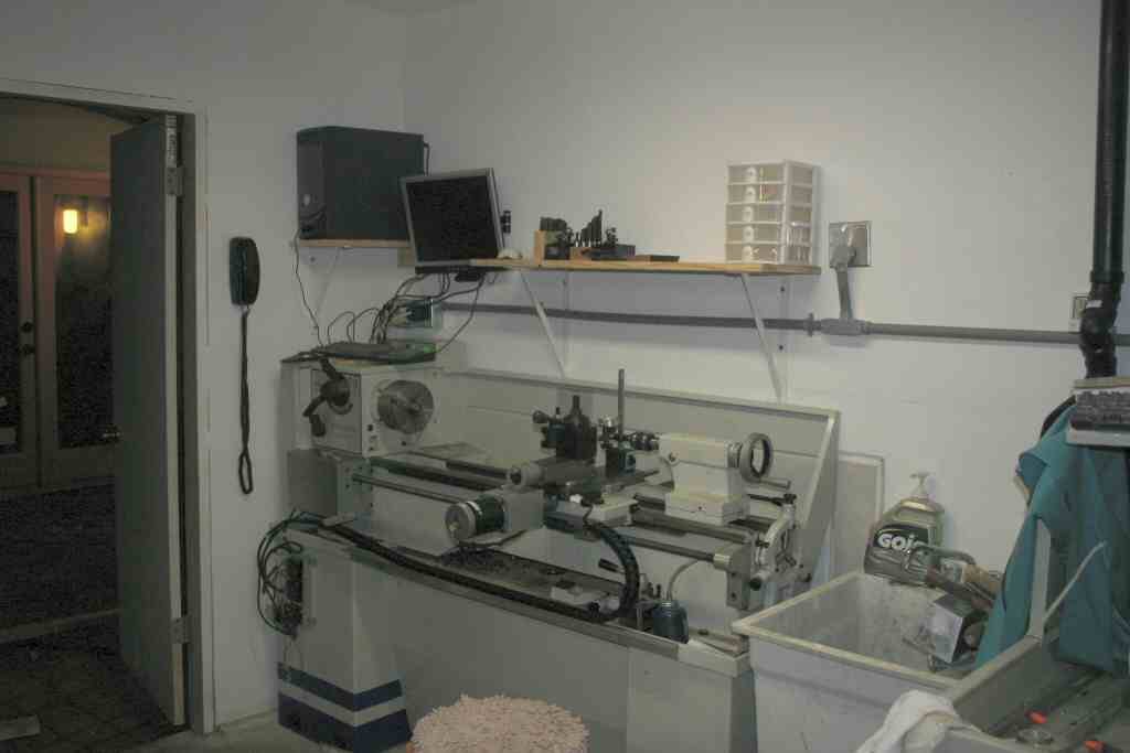
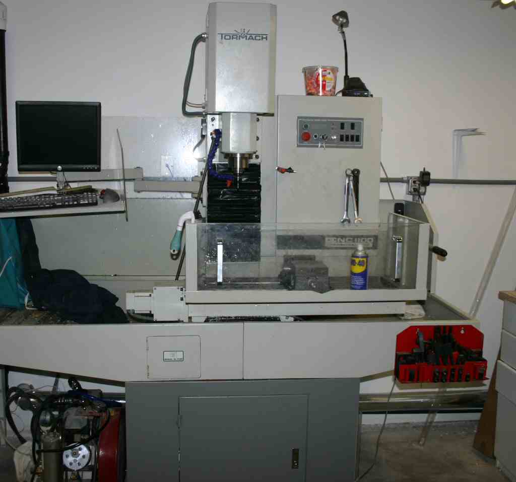
I spent the last weekend and most of Monday evening working in my Garage. Prior to this weekend all of the CNC tools were sitting in the middle of the room. I've now got them in their proper places.
The Lathe ..


And the Mill are in place...


There is still much to do all the welding stuff is still stacked in the corner.


In addition to working on the shop I've been having a lively E-mail design debate with a number of people. At one point it spilled over on Arocket.
I really enjoy the arocket discussion group, it a valuable resource that sometimes drifts off course...

Todays arocket topic If you are an American living in china and have some Chinese shop machine rocket nozzles out of oak logs have you violated ITAR and will you go to jail? Don't laugh it is seriously debatable that oak would make a good cheap ablative nozzle for a short burn solid rocket.

The "go to jail" part is not debatable ITAR is deadly serious and is slowly choking the life out of American space technology. Many European space projects have specific rules saying you can't use American parts because they then impose ITAR on everything.

Thursday, November 23, 2006

Thanksgiving and chambers.

For the truly obsessed a day off means spending the morning undisturbed with your CAD program and spread sheet. The virtual vehicle I presented last time has a lot of assumptions. One of my tasks is to verify the assumptions and reduce the uncertainty. One area of uncertainty is the weight of the thrust chambers and injectors. I spend the morning building a detailed cad model of my thrust chamber concept and using the CAD systems mass properties calculator to add up all the weights. Not counting the structure that ties the thrust chamber to the vehicle I get a fully accounted weight of about 5.3 lbs / 2.40 Kg This give me a chamber thrust to weight of better than 45. So my model virtual vehicle value of 30 seems reasonable. This weight is pessimistic as I have not figured out the details of the injector yet and used a 1 in (2.54 cm) thick copper plate as a astand in for the injector. The real world injector will almost certainly be lighter than this.


The basic chamber design is conceptually a copy of several different chambers that have been built over the years. It is a copper tube inside a slightly larger aluminum tube.The chamber is regen cooled with a graphite throat. I've been given drawings skectches and cad files from a number of people that have built similar motors. most of these motors have been larger, from 500 to 2000 lb thrust. Dues to scaling laws a smaller motor is harder to regen cool.
I hope to actually fire a small regen motor before the end of January.

Tuesday, November 21, 2006

A virtual vehicle


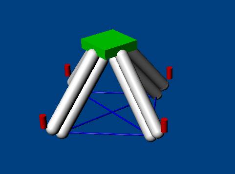
There are so many ideas and trade offs that it's hard to pin down a design. My current best guess for a vehicle is shown on the left. Its a lox ethanol vehicle with 4 250 lb thrust chambers. I'll try to describe it. The gray cylinders are aluminum irrigation tubing with hemisphere end caps. The red cylinders are the 4 motors. The green box is the payload and avionics. The blue lines are either spectra or kevlar lashings. Landing gear is not shown, but may be as simple as foam blocks under the tanks with additional shock absorption from give in the lashings. I like this design because I can test the tank and motor systems in a configuration identical to the final vehicle. I can even build up spare tank and motor assemblies. The other leading design candidate is a vehicle using 4 spherical tanks with four motors on the corners. In some ways a 50% scale pixel.

This is the first time I've actually drawn the vehicle in CAD. It has existed in many, many spreadsheets. The spreadsheet that goes with this vehicle can be found in PDF or XLS formats. The rest of this post won't make much sense unless you follow along on the spread sheet.

The top left of the spread sheet has a table of weights. I'm doing this both in Kg and pounds. To do any real physics type math MKS systems are better, but being an American I grew up with pounds and just can't kick the habit. The weights are listed along with the number of them on the vehicle. Several of the weight items are calculated. for instance the weight I assign to each thrust chamber is the peak motor thrust divided by 30. As the tanks have the most mass the tank calculations are more detailed. I use aluminum tubes where I can enter the length diameter and thickness, the spread sheet then calculates the weight and interior volume for a single tank. These numbers end up in the weight table. Finally I use the weight table and propellant mass. (labeled fuel in the spread sheet) to calculate the delta vee (DV) and number of hover seconds.

Some general notes:
  • Things labeled fuel really mean propellant. I've used an average fuel and oxidizer combined density of 0.8 gm/cc (At 1 ATM this would actually be about .92)
  • I only plan to fill the tanks to 90%.
  • The design includes 2 carbon fiber wrapped cylinders and a regulator to provide presurant gas to the point where the tanks are 60% full and then it runs in blow down mode from there on.
  • I've hidden a whole bunch of stuff in the "structure" item I hope to not need much structure beyond the tanks.
  • I'm assuming that I use aluminum tanks for both LOX and Ethanol, if I get into weight trouble I can build composite Ethanol tanks and probably save 16 Kg
  • I have a burst safety factor of 2.3 in the aluminum tanks. If I need more performance I can increase the tank and chamber pressures as the system can be pressurized remotely. The CF cylinders are DOT rated for 2200 psi, with a SF of better than 3 so I can probably get the extra pressureant I need from these. This would imply a remote presurant tank top off.
  • As per my communications with the XPC rules people any AST required safety shutoff valves etc.. are counted against the 25 Kg payload.
  • I used 25% of Cp for system and injector pressure drop.
  • I used 80% of the Cpropep frozen sea level ISP for my target ISP.

Comments are welcome.

Sunday, November 19, 2006

This weekend.


I indirectly worked on project related stuff all weekend. On Friday night My son and I drove out to the FAR site and camped out. The stars were amazing. All day On Saturday
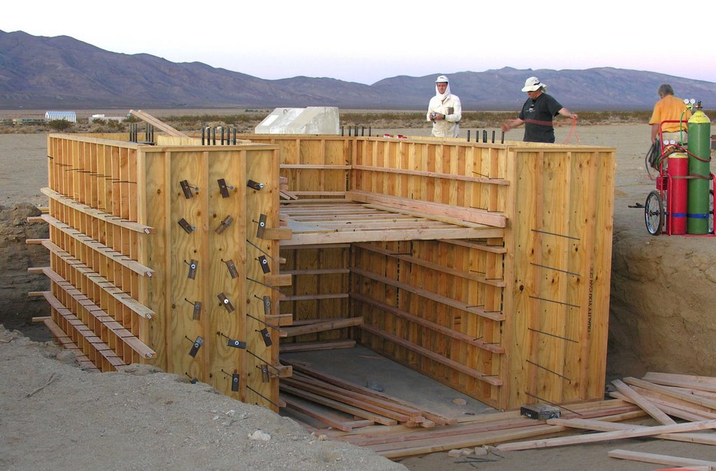
we worked on the FAR large vertical test stand. My son Paul welded and I did whatever to help. There were 8 of us who worked most of the day. The test stand should be ready to pour in another two work days. The picture shows the outside of the forms, Its going to be u shaped and the flame bucket faces the picture. there is going to be a 30 foot steel tower on top. Its being built for a nominal capacity of 30Klbs but it could probably do more for short periods.

Sunday, now that my final inspection is done on the house, I spent the whole day working on organizing things that could not be done before final inspection.

Thursday, November 16, 2006

A Personal Milestone.

On December 27th 2005 we started demolition for a major remodel of our house. We tore the interior down to bare studs. The plan was to finish by April 2006 , today November 16th 2006 we passed final inspection! This finally allows me to set up my shop properly as I can put up storage cabinets, move machines against the walls etc... I could do none of this until we passed inspection because the wall in question abuts part of the remodel and the inspector told me he needed to have access to the walls for final inspection! My wife is still painting walls and picking out flooring but the major part of my involvement is complete!

Tuesday, November 14, 2006

Not much work to report I spent the evening cleaning up the shop after the weekend. I do have an idea that sounds crazy.

Mylar is a type of polyester film. According to the article at Google Answers.
"Speaking with Dupont Technical Service this morning,
I found that PET films are virtually industructible
down to -250 degrees C. That is to say, the biaxially
oriented films (such as Mylar, Melinex etc) do lot
lose physically properties significantly as
temperature is reduced. "

Polyester film is closely related to PET soda bottles. It can be readily glued with the proper glue (gorilla glue is one brand) The water rocket people have explored this area extensively.
A gentleman at the 2006 space access had done some experiments with LOX and plastic soda bottles. He found they worked well and remained flexible atLOX Temperatures.

One of the problems of building low temperature composite structures is that they get brittle, and then crack loosing their strength. They also suffer from dissimilar temperature coefficients between their carbon fiber structure and their, usually aluminum, liner.

What if your structure was just a bag inside a mesh support? This is much like a counter pressure space suit instead of a full space suit. One needs to create the mesh out of a fiber that is very light and stiff enough that the liner will yield into the fiber before it fails.

The strongest fiber currently known is spectra 2000, it has a yield of 3.2 Gpa and a young’s modulus of 124 GpaIts also lighter than water. For comparison Titanium has a modulus of 120 Gpa so spectra size for size is stiffer than titanium. It’s also size for size 2X as strong as steel. Spectra is slippery so it’s hard to glue into a matrix, but a woven sleeve of spectra over mylar might make an interesting tank. A high perf tank made of soda bottles and kite line.Yea that is crazy.


Sunday, November 12, 2006

A weekends work.

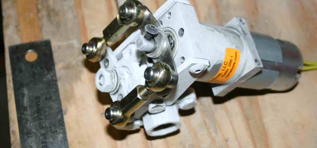
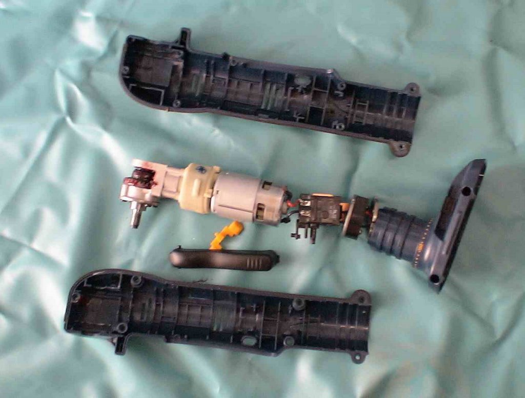
I worked on this all weekend and I've machined the parts for 4 valves. I've fully assembled one and done some preliminary testing, so far it looks good. I promissed some pictures. The first picture on the is the Ryobi drill taken apart.


The next picture is the set of machined parts nevessary to turn this into a valve driver. The part on the left consists of a custom piece bolted to the remanats of the drill chuck that was turned down.


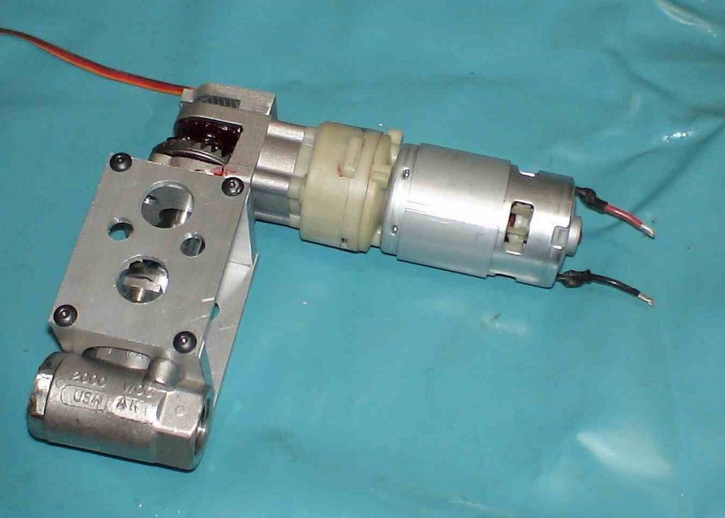
The next picture is an assembled valve.


The motor power wires are on the left, the small wires exiting the top go to the magnetic position sensor that sense a small magnet glued to the top of valve shaft. I've built for of these. When I get the electronics to operate them done I'll test one with LN2 and see how they work.

The finished valve weight about 1100 grams.
The machined parts are about 170 gm and the just the motor without any thing else is 350.
so there is some room to use a better (brushless ) motor and trim some weight.
The final valve could probably end up under 1Kg.

Friday, November 10, 2006

The CNC myth.

For the last two years I've had some kind of CNC machine in my Garage. I started with a small Taig Mill and moved up to the tormach. When people learn you have computer controlled machine tools they bring you all sorts of broken things to replace. They think that a CNC mill is some sort of magical printer that makes metal parts. The process of using a CNC machine requires that you know how you would machine the part by hand.

If you don't know how to read or write, a word processors is no more useful to you than a typewritter. (if you can't read or write both are useless) A CNC machine is a lot like a very dull, but very dependable helper. You tell it exactly what you want to do and it does it, no more no less. If you don't know what to tell the machine it's useless. For an overview of using CNC for a different project see my balsa wing rib cutting page.

Last night I finished the brackets and parts for my valve. In removing the chuck from the disassembled drill I broke the planetary gearbox. It' has a plastic outer case that is plenty strong when in its outer drill case, It's not so stron when unsupported. I've contemplated making a new case out of aluminum, but that would be an all day task. I'll see if the plastic one ends up being serivicable.

I'll post a bunch of pictures and a short video of valves on Sunday.

Thursday, November 09, 2006

Valve frustration

In a large way rockets are just plumbing.
Tanks pipes, valves and showerheads.

Rockets are weight sensitive, traditional industrial plumbing is not.

It would be nice to use an off the shelf valve.
Off the shelf controllable valves are slow and heavy.
Real aerospace rocket valves cost more than the budget for this whole project.

So I've been trying to build valves.
The first attempt looked good they were reasonably light and fast.

My son and I built a whole test stand based on these valves, it was ready for a static fireing in late July The valves froze up when tested at liquid nitrogen temperatures.
In messing with these valves I now have a pile of dead hitec robot
servos. the servo is just not going to cut it in this application.

(I've been mostly working on other things in between July and now, so I have not spent 4 months playing with valves, more like a month.)

So I'm now back on to valves full time.

I'm a firm believer in the markets ability to optimize things and create cool engineering solutions at low cost if the volume is high enough.

One key is to discover these items and use them in the project.

In that light I've been looking for a tough lightweight valve actuator.
Whats lightweight, powerful and tough? Battery operated hand held tools.
After buying disassembling and destroying a large number of Home Depots finest
hand tools I've settled on a Roybi 18V P240 right angle drill, very tough well built and
not too expensive.

The first thought was to just grab the valve stem with the drill chuck and go from there.
this works when hand held as your body provides a little bit of compliance for misalignment.
When you build study brackets to tie the drill down it breaks/jams things.

The second thought was to remove the chuck and machine an adaptor that provides for some misalignment and threads on where the chuck used to go. I almost finished that assembly tonight. I'm short one hole, as the plate that mounts to the valve stem is stainless it work hardens and I broke off my last 8-32 tap drill in the bracket. I was hoping to test this tonight,
but I'll have to get some good carbide drills and redo that plate Friday.

If the ryobi drill does not work I have one more valve concept to try. I'll spend another 3 weeks on valves and if I can't make it work by then I'll bite the bullet and buy the heavy industrial valve actuators like armadillo is using. The results from this will effect my fundamental vehicle design as they are heavy and you need at least 2 per motor. I was hoping for a small 4 motor vehicle with fully differential throttling.

When I get a valve fully assembled I'll post pictures.

I need to move on to engine tests, igniter development and tanks.
I have bits and pieces ordered for all of these, most due in around the end of the month.

Welcome to all

I started this blog as a personal journal to
document my quest to compete in the Lunar Lander Challenge.
I asked a couple of friends if I should make it public, they both said yes so here it is.

It is not a literary master piece.
Its not going to be an opinion journal, its going
to be a log of daily thoughts, decisions and experiences along the journey.

It will make much more sense if you start at the bottom and read your way to the top.

Paul

Early morning with the FAA.

This morning at 6:00am I had a conference call with the FAA/AST.
I think it was a good first discussion.

One bit of good news is that they can still issue "burn time waivers"
or officially license waivers. This is a lot less onerous than doing the full
environmental review called for by an experimental permit.

I was hoping to get endorsement for my concept of drawing a bright line between operating and safety systems and qualifying the safety systems and leaving the operating stuff alone.
They did not really say no, but it was clear thats not the way they want to proceed.

In some places I was hoping for a little more direct guidance about whats acceptable.
Some of the conversation went like:

Question to FAA:What would you like to see to prove X?

Answer:Its your job to convince us of X.

The answer is completely correct and almost useless.

Its all part of the process and my current action item is to generate a hazards and hazard mitigation document.

My short version of the document:

Hazard: The Vehicle or parts of the vehicle can leave the defined operating area and hit
something it's not supposed to.

Mitigation: Add redundant safety abort systems that will Kill the vehicle before it does so.

They want a bit more detail, I'll have to work on that. :-)

Wednesday, November 08, 2006

Time and commitment.

Monday night I worked all evening to make some nice aluminum brackets for our test valve.
I went to bed at 12:30 and got up at 5:45 to keep my appointment at the Gym.
By Tuesday evening I was useless and did no work. I see its going to be a challenge to
both keep the commitment and to throttle the effort so as not to burn out.

Today I finally got the FAA to engage in some discussion and learned a valuable fact.
They are much more open to talk rather than respond to E-Mails as it leaves no record.
I've scheduled a conference call for 9:am EST Thursday (6 am here) so maybe I'll finally make some progress. My agenda for the call is as follows:


Three specific Items I'd like to discuss, and a few more if time and personal permit.


1)Is my concept of having two redundant flight termination systems
that are completely separate from the vehicle operations hardware and software acceptable?

Specifically:
System 1 continuously calculates the instantaneous impact point at 5Hz
and terminates the flight if the IIP hits the predefined defined boundary.

System 2 Is a commercial PCM RC receiver that terminates the flight on command or on loss of signal.


2)What limitations are necessary for staying within the 14.99999 second rule.

Can I carry more than 14.999999 seconds of fuel with a hardware timer that terminates
thrust after 14.999999 seconds of burn time?

Is sensing valve position sufficient to establish burn times?

Is a post burn cool down purge with water and/or inert gas counted against the burn time?

I want to test the vehicle at full gross takeoff weight with the same dynamics as
a fully fueled vehicle. I'd rather not have separate non-sloshing weights as this is an
unrealistic test.


I'd like to set up two temporary metal road plate pads at FAR and


3)What are the requirements for tethered operation?
Rather than do serious worst case mechanical tether analysis can I have the tether carry an electrical circuit, if the
circuit is broken terminate the flight.


Additional items...

Hardware design items:

My intent is to make the safety termination systems separate isolated battery powered
units. The only external connection will be a fiberoptic status output so the units can report battery condition
and self test completion to the outside world. Fiberoptic is chosen as there is no physical way to transmit
electrical transients back into the units that will kill them.

I plan to do full environmental shake and bake qualification on all safety termination systems.
I'd prefer to do this with self constructed temperature chambers and vibration tables,
but If more formal methods are required I'm familiar with the process as I used to run a
"shake and bake" environmental stress screening operation that tested avionics for the Navy.


How would the FAA like to see positional IIP limits input into the system
Some possibilities:
Physically carry the box to the boundaries of the termination area.
Establish a center point by physically transporting the box there and then draw boundaries.
Enter the boundaries from a map or other source of geographic data.
Can the boundaries be simple rectangles?
Convex polygons?


I realize that calculation of Ec is not required for an experimnetal permit, but I expect that one will be done
in any case. Is there any benefit in qualifying sub components in a real world environment and
demonstrating a low probability of failure, showing operational reliability by test?

I'm thinking about putting the navigation,stability,control, and safety termination systems on a RC helicopter
and having them fly vehicle competition profile hundreds or even thousands of times.

Any benefit in having a RC plane or helicopter fly the boundaries of the IIP box for visual verification?


From todays phone conversation it is clear that the FAA does not like my choice to
do all my testing at FAR under the 15 second rule. With a limited budget I just can't afford
to do it a Mojave without some external funding. If we get to the point where that becomes necessary maybe we will have enough visible results to attract some funding.

Specific Progress Tuesday and Wedensday
I finished up the PCB design for my helicopter tester.
I hope to fly an RC helicopter with the same telemetry and control as the rocket and
start testing and writing the command and control software. I will see is my tine Trex 400 can lift the equipment otherwise I will need to buy something bigger.

Tonight I hope to finish my first drill driven prototype valve.


Paul


Monday, November 06, 2006

The first big single purpose check.

Today I sent the xprize foundation a 2K check,
my first downpayment on the project I'm on the way to being an
offically registered partcipant.

I'm also starting to make a slight bit of technical progress.
This weekend:
I met with seveal other rocket nuts at the FAR site and discussed designs and ideas
with Charles Pooley and Ken Mason.

I spent sunday finishing my Lathe. I have a 13x40 birmingham manual lathe.
I had the mechanics converted to CNC by Industrial hobbies, they did all the mechanical work and I did all the wiring and electrical. I've had the Lathe for a year and never got around to finishing all the wiring. Last night the lathe cut it's first metal, and all of the CNC parts seem to be working.

Sunday evening my son and I did some work on converting a Ryobi right angle drill driver to a
valve driver. We mounted GMW angle sensors on the end of the spindle and used a Netburner and a Scorpian XL driver to drive the valve. With simple proportional control it overshot
unloaded and did not do well when loaded up. In the next few days we will ad the rest of the PID
constants and see how it works.

Thursday, November 02, 2006

Decisions already made...

On my very first post I posted a list of questions and decisions
that need to decided and answered.
In reality some of the decisions have been made by defualt.

Where can you test a rocket?

All of the significat testing will be done at the FAR site.
What will the AST (government) let you test?
I just don't know yet. All of the significat milestones can be tested under the 15 second non-licensed rules. The 90 and 180 second hovers can be done on a tether.
Do you build things in your shop or hire out to have part made?
I've spent the last two years equiping my shop, so for me this is a no brainer.
I have a converted 13x40CNC lathe and a Tormach PCNC100.

W
hat parts do you buy?
Anything youcan. In reality . Maybe some and some elctronics assemblies, but most of the stuff is built from scratch.

W
hat parts you design and build yourself?
Almost everything.
What fuel do you use?
While I've toyed with hydrogen peroxide, the reality is that the only resonable propellants are something and Lox. for ease of development something is almost certain to be good old moonshine otherwise known as
ethanol..

Whoose techncal advise do you trust?
I trust the guys at flowmetrics.
I trust the written wizdom of John Carmack and the Armadillo team.
I trust the Masten folks.
At some level I'll trust anyone that has actually built a biprop motor and run it.

Do you buy an almost working design form a competitor?
One of the other teams has a nice motor design they are willing to sell me at a resonable price.
the only problem is that its the wrong motor. It's the right size, but its too high of pressure to run with a pressure fed system capable of doing 190 seconds. It's damm tempting, but
not until I try on my own and fail.

Do you have the budget to do this at all?
I hope so, please see the previous post.

The background and the commitment.

I've always had the feeling that the "average" life
was somewhat of a waste. I've always had big dreams.
One of my earlier unfinshed projects can be found
here: Solar Glider
This was an insanely difficult project that consumed 5 years of my life.
As you can see on the web page I have a working design, but I
fell short of my record setting goal.

About the time I last flew the solar splinter I wandered into the
flowmetrics shop (www.flometrics.com) and discovered the SDSU rocket project.
Here were a bunch of inexperienced students building aliquid fuel rocket.
I was impressed, but on closer inspection it did not seem to look that hard.

So for the next two years I provided them electronics when they launched
and spent a lot of time talking to the wizards at flometrics.
I also bought every book on rocket motor propulsion design I could find
and this has been my bedtime reading for the last two years.

By reading, studying and watching others (principally armadillo) I've come to
believe that a normal humans with moderate funding can do significant
rocketry. As that realization slowly sinks in, I've equipped my shop
with what I think is necessary to actually build rockets. CNC lathe, Mill, and good quality welding equipment. As this realization slowly comes to be I also start searching for a worthy
goal.

My inital thought was to do ameateur sputnik. Build a rocket in a garage that can reach orbit. Not with any payload, just a 100 gram tranmitter that circles the globe and
transmitts "Normal mortals can reach space". This is a very hard goal it has significant technical
and significat regulatory issues. I also believe that done as an ameteur project it would take about 1M$. Too hard, too much $ and too lofty.

As I'm in the midst scheming how to do this, I hear about the Nasa/Xprize lunar lander challenge. It looks like the prefect project.
It's hard, but not impossible, the regulatory burden exists, but it is not insurmountable.

So this has become my quest. My guess is that it will take $100K to build a working vehicle that can do the task. I think it will also take another 50 to 100K to prepare for and campaign
the vehicle at the xprize cup. If I live frugally for the next year I can spend this much without
causing any permant financial hardship. the whole family is now on a budget.
I have done things like cancel my dish network subscription, if I'm going to do this I have no time for TV.