Monday, October 03, 2022

Solar Plane continued...

 A solar plane with multiple rows on the wings will have differnt illumination on each row and on each wing. The last plane had 3 rows x 2 wings. So 6 total channels of power point tracking.

I think the new design is going to be slightly smaller with two rows.  The 12 or 13 cells in series will have a max output voltage of ~7.5V.  So my system battery/bus voltage will need to be above that.
I'm thinking 6S LiIon.

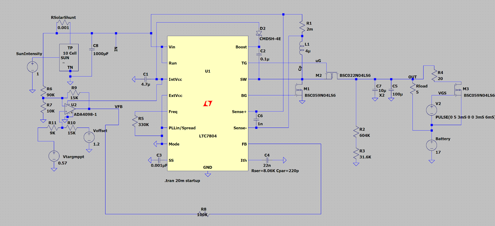
So I wanted to simulate the power circuitry of the solar mppt system.
I used the LTC Spice and built a singe solar cell model:


I then combined 10 of these to be a 10 cell array....


Then I used the LTC7804 test jig as the basis for a full up simulation.


So instead of regulating the output voltage it now regulates the input voltage.
The op amp on the left side inverts, amplifies and offsets the cell array voltage and adapts it to the LTC7804 1.2V reference.

The two voltage sources on the left side Vtargmppt and Voffset will be combined into a low power precision DAC from whatever microcontroller I choose to drive this mess. (One could thevenize the resistance and voltages to form a single source, but since no significant current should flow into the
+ node of the op amp the resistance probably does not really matter.
Basic power path is decided, now to make a couple more decisions and prototype in the real world with a set of real cells.

For deciding the MPPT tracking point there are several choices:
Random path search.
Percentage of Voc (what I chose last time)
Table of V vs Cell temp.

I'll play with all three modes... I'm hoping the cell temp vs V works well.
The data sheet says Vmppt is  5.8V at 25C and is -1.84 mv/deg C.

On the airframe front I've also been playing with basic aircraft layout using
XFLR5 to design the airframe.  While a solar wing really wants to be rectangular the
improvement in minimum sink with an additional tapered panel is so large that its probably worth doing even if it has no solar cells. (Winglets have same effect, but shadow top side cells so that does not work.) 

I really need to get a good target weight I'm comfortable with so I can have a target design and then determine gram/watt sort of sensitivities to make proper power/weight trades.
an example trade would be to add cells to the tailboom. Hard to balance as all the weight is aft and 
so will likely need added wt forward. The weight and drag acts 24 hrs a day. Added power is only useful for 12hrs and then requires added battery wt to use the excess power overnight.

Adding panels in the taper tips are at differnt angle/solar incidence than the main wing cells.
So they need their own mppt tracker. does it make sense to add a tracker for 15W of cell
running at 1.5 to 2 V so efficiency will be poor. With the LTC7408 it has synchronous reftification so that should help at low voltages.  (Inductor will be smaller as well).

Speaking of inductors I've gotten proper aluminum magnet wire quoted at $2.20/ft and 1Kft minimum order.  So I've 3d printed some air core toroid forms and wound un insulated aluminum craft wire on these...made some light inductors....        

Trades/Trades/optimizations as far as the eye can see... More later.


Saturday, September 17, 2022

Solar powered planes.


 In 2004 I built a solar powered RC plane.
You can see pictures and read about it sees some pictures and relive its sad end here: Old web page from 2004

I'm going to try this project again.

In the 18 years since this flew a number of things have improved:

  • Microscopic autopilots for RC planes are COTS. (mRo <5gm  etc)  I  no longer have to build my own.
  • Long range RC control and telemetry links are COTS (Crossfire, ELRS, Dragonlink)
    I no longer have to build my own.
  • The solar cells have improved. The new SunPower C60 cells are 6.5 gm 3.5W 22% efficient and Flexible. The A-300 cells I used 18 yrs ago were:12 gm, 3W 20% efficient, and pretty rigid.

Old cell left, new cell right

The new cells are pretty flexible.


On the old plane I had 3 rows of solar cells on each wing. Each row was wired in series to make about 6.5 volts. I then built a 6 channel MPPT (see: wiki MPPT)

The schematic for one channel of my MPPT:

The full 6 channel unit:


This MPPT is setup as a boost converter so the system bus or battery voltage must be above the voltage of the solar string. It also allows solar strings of varying size to feed a common bus. IE I can have a 4 cell panel on the tail, a 4 cell panel on the wing tips and a 2x 10 cell panels on each main wing.

There are lots and lots of interesting tradeoffs in this space.
At minimum power the wing drag is primarily induced drag. One reduces induced drag by making the wing have a very high aspect ratio and an  elliptical lift distribution.

If you want the absolute minimum power you want a  really high lift airfoil like:
S1210:


Selig S1210

Yet look how thin the trailing edge is and how hard that would be to build lightly.
Heavily under cambered airfoils also have really high pitching moments.
(Meaning the airfoil wants to pitch forward and this must be resisted.)
Put this airfoil on a really long high aspect ratio wing and its not unheard of for the wing tip to fail in a downward direction... (The airfoil tip tries to twist forward twisting the wing, enough that the wing tip on light structure is now lifting down and bad things ensue.)

One could choose an airfoil designed for flying wings (now or very low pitching moment) like 
MH60:

Much easier to build a very light structure with this trailing edge and the torsional rigidity of the wing will matter a lot less.


The minimum power airfoil (assuming an infinite wing) is  where Cl^3/2/Cd is maximum.
For the  1210 :  109 For the MH60 its : 68....

So the minimum sink is roughly proportional  to weight ^ 1/2  Min power is thus weight ^(3/2)
So for a 1000gm airplane you could add a couple hundred extra grams and be even.

So if one wanted to fly over night.... using the potential energy of the aircraft as a battery  sink rate is only effected by wt ^1/2 where if you wanted to fly all night  at constant altitude via battery then assuming the battery is 30 to 50%  of the mass (reasonable assumption) then each extra gram of structure is bad by an additional requirement for more battery.

Like I said a really complex trade space...


Looking at the professional Aerospace for hints/clues is not really helpful...
Helios was a flying wing, that failed due to complex aerodynamic, structural, and turbulence interactions. See Report here

The Solar impulse and Airbus Zypher both chose a more traditional aircraft platform.