Monday, April 23, 2007

An overdue update...

This last weekend I went to the NG-LLC summit at Holloman airforce base in New Mexico. I have not been officially notified that this is not secret, but I found a bunch of references to the 2007 XPC being at Holloman on the web via Google so by the terms of the NDA its no longer secret. We got to chat with a number of the airforce people and it was a productive meeting.
I think it will be cool to fly at the base and I'm a bit worried about the red tape.
The Airforce Officers think it will be cool for us to fly at the base and are a bit worried about our lack of red tape... All in all a good balance. The Base looks like a good site if the MPL insurance issues can be worked out. A single F117 stealth fighter inside the NG-LLC flight hazard area would make the Maximum Probable Loss so high we could not afford insurance....
(I believe that holloman has the only F-117 fighter wing.) So the FAA, XPC and air force are playing with maps and trying to put us where:
  1. We cant hit anything valuable.
  2. The crowd can see us.
  3. We can't hit the crowd. (see #2)
  4. The Airforce does not have to move anything unmovable.
  5. The operating area is not a three day drive from the staging area.

Tonight I disassembled the motor I ran for 106 seconds to look for the leak.
Its very obvious that the oring was cut on the screw holes during assembly.
Charles Pooley nailed it for an explanation. I'm going to rebuild that part and try again on Saturday.


I bought a new(to me) truck since the old one died and I wanted something with a tad more creature comforts for driving to the test site. An 18 year old truck with stiff off road suspension and no air conditioning was a bit stressful. I bought a used Dodge RAM 1500 Quad cab. Its a nice looking truck, I almost feel sorry for what we are going to do to it in the next six months.

Lastly I sent my FAA/AST contact a mostly complete draft of my experimental permit application. This has been a real challenge for me as I would rather chew off my right arm than work on paper work. Many thanks to Mike Kelley (who has been asisting me in this effort) for listening to me whine and offering useful suggestions.

Sunday, April 15, 2007

Seal problem looking for suggestions...

In reviewing the video for Saturdays test I realized I have a seal problem.
The first short test:Video
The second long test:Video

If you look at the very bottom end of the motor on the first run there is a minor leak/spray where the throat seals to the outer aluminum. On the second run this is a huge gushing torrent until the copper throat gets hot enough to seal. (You can also see where this leak seals up on the chamber pressure graph)

The seal is is a a 1/8" 0.139 nominal high temperature o-ring.
The mechanical details are shown below. The pressure is about 350 PSI not trivial, but not huge either.The clearance between the copper throat and aluminum outer closure in almost zero. The motor was assembled with a rubber hammer its very tight. Its quite clear that the seal failed after the first test. Any ideas on what is wrong?

Saturday, April 14, 2007

106 second burn Good Motor/Bad Motor


Good Motor:
We ran the 250lb regen motor again today. We ran from full tanks to depletion at full throttle, between 105 and 106 seconds. It lit a bit hard, and it had a bad fuel leak, but otherwise it was an almost perfect run. The video up on youtube .

Bad Motor:
On the way home going up the hill on hwy 14 we blew a head gasket in the truck. It took 6 quarts of oil and 2 gallons of water to get home.

Data:
The data is below. the Load cell gave me qualitatively reasonable data, but the calibration can't be right, with the measured chamber pressure and throat size, I'd see more thrust with no expansion cone at all.... alas there is something I don't understand about the load cell calibration.

Saturday, April 07, 2007

Working on paper work.

Its about 195 days till XPC, so I need to get my AST application in a
sufficiently complete state to start the clock running. I've been working diligently on that. (Its up to about 50 pages and I still have at least one hard section still to develop.) I will publish what I submit and any official correspondence from the FAA here. I will not be publishing the rough drafts and the E-mail back and forth as I don't want to inhibit the communication.

I spent this evening working on a solid copper throat and closure assembly and I should be ready to test again on Sunday. It will be quite a treat to be ready for a Friday outing to test on Sunday!
I might even get some sleep before driving to the desert next weekend.

As anyone who knows me personally knows, I'm not much for sartorial splendor, I do have a never ending collection of tee shirts with thoughtful sayings on them... Like:
Top 10 reasons to procrastinate
1.
(The rest of the shirt is blank)

Given that I think its time I had some Unreasonable Rocket Tee shirts made.
I'll probably do this through Cafe press so if anyone is interested say so in comments and I'll post the design link.

Saturday, March 31, 2007

Testing 3/31/07


Saturday we fired the 250 Lb motor with a new all copper pintile injector. The top end of the motor and the chamber wall worked fine. The Throat/end closure leaked and we melted the bottom end of the motor. It ran for 24 seconds, but the video camera died 20 seconds into the firing. The video is here.

After looking at the data, the chamber pressure started declining almost immediately, so I think the throat was coming apart as soon as we started. We still did not get any load cell data, the load cell worked in the shop, but not when the rocket was running. We have gotten this result twice. The Fuel feed pressure was also very noisy. In the chart below the Tank pressure sensors measure the tank pressure and the feed measures the pressure at the input to the motor after the throttle valves. At the end of the run the Lox tank and feed pressure drops quickly as we vent the tank, but the fuel pressure does not seem to change much. This is because we vent the fuel tank utalage into the motor for purge.

We will make a solid copper throat/chamber assembly and either test next weekend or the following week. It will depend on if I can find a 1st class Pyro op for this coming Saturday.
(It looks unlikely).

Today I started seriously looking at the paperwork necessary for my AST license. It seem like an appropriate day to start ;-) I wrote the beginnings of a hazard analysis and started looking at the procedures and verification processes necessary. Toward that end I also made a slightly more accurate rendering of the vehicle.

Sunday, March 18, 2007

Good Test Results...


The testing went well on Saturday.
We fired 1/4 of a vehicle. We had some software sequence problems that caused it to start roughly but we ran it for 16 seconds with no burn through or other damage.
The Video is here: Video

Sunday we disassembled the motor and analyzed the data. There is good news/bad news.
Good news, the regen motor shows no signs of melting. The bad news is we looked at the data and the presurization problem was more severe than we thought. We never got up to operating pressure. The operating pressure is supposed to be 80 to 250PSI we ran it from 40 to 120 during the test. So we did not run it anywhere near full throttle. This is actually useful data as it shows the engine is stable at low feed pressures, all the way down to 50 PSI. We got no load cell data.


We also fired the 650 Lb Ablative we tried to fire a few weeks ago.
That video is here

Friday, March 16, 2007

We have been busy...

Its 11:33PM and we just finished packing the truck.
Saturday we go out to the test site and test 3 things.

1)The 650LBF motor that we tried to fire last time.

2)A 250Lbf Motor in exactly the configuration we want for the NG-LLC.
This includes flight weight tanks and a torch igniter.

3)My Compressed Air stability software development vehicle.
(See:Here)

The hardware is all 100% ready, both items #2, and #3 need a little software tweaking.
So rather than stay up all night, I'm going to get some sleep and work on it at the site. I may spend Saturday night and Test on Sunday as well.

I'll post video, results and news Sunday or Monday evening. I'm going to Space Access in Pheonix next weekend so if any regular readers are going make sure to say say hi.

Friday, March 02, 2007

Our first Mach diamonds.

Tonight I tested my igniter. It fired correctly on the first attempt.
I did not get chamber pressure so I need to figure that out before I fire it again.
In any case we made our first Mach diamonds.

Enjoy the video...(You tube)
Larger Version on my server.

Wednesday, February 28, 2007

Injector Version 2 flow tests


Based on my previous testing and some advice I received on Arocket I built a new injector.
Its got a smaller pintile and a tapered out area behind the annular gap. the annular gap is only 0.050 deep. the new pintile is only 0.400" across. I flow tested it tonight and the Fuel came out perfectly within 1.5 % of where I wanted. Well within my experimental error! The oxidizer is about 10% low (Meaning I'll need to run my pressure 20% high) Its good enough to test as is. The visual quality of the combined spray cone is very good. I took a fast flash picture of the result its on the left.

I also took a picture of just the fuel orfice


I also tried to take a picture of just the lox spray and got everything in the entire shop wet. Sorry for the bad quality, but after wiping the water off of my Lathe and Mill I was not about to try to take the picture again.

Thursday or Friday I'll try to braze the igniter mount on the the assembly and I'll have a new motor by the end of the week end!

Monday, February 26, 2007

How I got started...

I realized that normal mortals could do liquid rocketry after spending some time with the SDSU rocket team. They have also started a blog, only one post so far.

After watching them build and fly stuff and discovering the Armadillo blog I was hooked.

Update on the week end:
  • Bob welded up two tanks and was almost finished with the third. When the tanks are ready we will have them heat treated and test one to failure.
  • My son went into production mode working on making a batch of 12 of the tonegowa servo valves.
  • I worked on designing and fabricating a new pintile injector based on our flow tests and some feedback I received on Arocket.

Wednesday, February 21, 2007

Some Hardware.


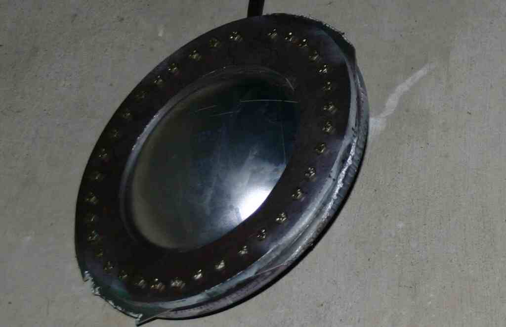
Here is a picture of my Pintile injector.
To give you an idea of scale the tip sticking up in the middle is 0.675 inches across. The small holes are 0.029" I don't have a water proof digital camera so I was unable to get pictures of the injector flowing.


I went to harbor frieght and bought a small sandblasting unit to use for pressurized flow testing. It has a large pressure tight opening on top to rapidly refill with water. It makes a heck of a squirt gun. Using that I flow tested both my lox and fuel flows for my injector. (I tested using water and adjusted the numbers for density) The fuel flow was about 35% low, and the lox flow was about 11% low. The 11% is close, but the 35% is off more than I would have expected. I'll try opening up the annular gap a tiny bit in next few days. It will be very hard to get it re centered. I'll probably end up making another one in the next few days .


Lastly here is a not quite ready to be fired picture of my igniter. The Aluminum box it's leaning on is the electronics for driving the shielded sparkplug.

Tuesday, February 20, 2007

Quick clarification


Carl asked what keeps the fuel plate from moving back and collapsing into the pintile. The cut away view did not show the arms very well, but this view with the pintile turned tranparent does. the three arms are a solid part of the fuel orfice plate. They also align the two plates. The outer aluminum casing is turned off in this view.

Monday, February 19, 2007

A New chamber design

I put together a short outline of my vehicle and the safety systems to present to the faa/ast when I was in DC. There are some typos, and a couple of things missing, but its probably worth publishing. astpresnt.pdf.

I have a bunch of new hardware that I will post pictures of in the next few days. I've designed a 250 lb thrust chamber. Its a copper tube with an outer aluminum shell. I've designed the pintile injector and and I built one this weekend. The hard part for a motor this small is keeping the annular alignment between the pintile and the fuel plate the gap is nominally 0.0062" all around. This seems insanely small,(The 25 #69 lox holes in the pintile aren't exactly large) but I did the calculations a bunch of times and it seems to be correct. I machined an alignment step on the pintile and a corresponding recess in the plate that forms the annulus. Goal was to hold the annulus size to +/0.0005" and I think I got it. That is the limit of my measuring equipment.
The alignment recess and step are close enough that if you heat the the plate to slightly warm and cool the pintile to slightly cool they slide together. At the same temperatures they are a tight press fit.

The O-rings I had on hand were not correct to seal in my injector test fixture so I did not get the satisfaction of seeing the injector work. (the o-ring sealed enough for my to try it and get all wet... again.) In the next two days I will be flow testing the injector and I'll post pictures of the hardware.


On the left is a split rendering of the chamber design. To give an idea of scale the inner copper tube has an ID 0f 2 inches. I still have not decided if the throat will be copper or Graphite.
I will try both. The chamber needs to throttle from 80 lbs to 250 lbs. so I set this up to be 50 to 150 % of nominal. Thus the chamber is nominally laid out for 166 lbs of thrust at 166 psi expanding to 12.5 PSI. (the ambient pressure at Las Cruces.) Theoretical ISP at this low pressure is 216 frozen, I'm hoping to realize 180+. The pintile orifices are designed for 32 PSI of pressure drop at the desired flow rate. The orfice sizes were calculated with a discharge coefficient of 1.5. We will see how close I got when I do the flow testing this week. I'll gladly post my notes and spread sheets for all of this, alas I fear they probably won't make any sense to anyone but myself.

I resurrected the lrd (liquid chamber design program ) from the rocketworkbench. I modified it with two additional parameters. water_percent to allow you to add water to your fuel/oxidizer and exit_pressure to set an exit pressure other than 14.7 psi. The program executable is here and an example input is here. If anyone wants the modified source code I'll send you the microsoft visual C 6.0 project with all the files in it. (this also builds cpropep, but the cpropep I built seems to go bboom when I try to run it. I haven't taken the time to figure out why. In the end it turned out easier to use the output from cpropep and a spread sheet.

Sunday, February 11, 2007

Saturdays Testing(updated II)

From the lunar lander project perspective everything on Saturday went perfectly. The systems all worked as designed, we had no frozen vales, instrumentation or computer problems all of that was flawless.

The real story is we were testing an older engine design that used a pyrotechnic igniter and we and that failed to get it lit. So some time in the next 24 hours I'll post a very boring video of Lox and alcohol coming out of a motor in unburned form.

If we had more Lox we would have tested again, but we were using the left over Lox that had been delivered for a different project. By the time they were done there was less left than expected. My son was very disappointed we did a lot of work and got no flames, booms or other intersting pyrotechnics. I was happy with the result because the components of the test that apply to the XPC project all worked flawlessly.

Here is the test video, kind of boring, I've also uploaded an unrelated video of other rocket things...

Saturday, February 10, 2007

Its 2am the thrill is gone....

A number of knowledgeable people keep telling me to start fireing a Motor, any Motor to get experience with liquid rocket motors. This summer my son and his friend Jason built a test stand and rocket motor. I built the Injector Plate for it. Due to valve issues it was never run.
We have put new valves on it and its ready to test. Since our test site has a lot going on this weekend and we decided this would be the weekend. Alas everything takes longer than expected.
One minor example... I'm a founder at Netburner, so the electronics that runs the test stand is all based on Netburner modules. Well the sample code that I brought home this evening to use uses a relatively new NetBurner feature so the code release that is running on my laptop does not support it. So step one is download a large file and reinstall tools... It went down hill from there,I think were finally ready to go, but the garage looks like there was a tool explosion...

It's 2am and I get up in 4 hours, as the song says its 2am and the thrill is gone....

Sunday, February 04, 2007

Quick Update

A quick update before I catch a plane.
  • Tanks: I found a place where I can order thicker T0 aluminum, the aluminum for thicker end caps will be here on Feb 7th. I also found a local place to do post weld heat treating, this should get me to my goal of 500 PSI with the aluminum tanks.
  • Igniter: I fabricated an Igniter using orfice sizes and the basic construction concepts that John has documented on the Armadillo updates. The Igniter, solinoids and ignition system is lighter than the weight allocated on my virtual vehicle. Having something tunr out lighter is always a good thing. I'll test it late next week.
  • Paperwork:I'm flying out to DC to attend the AST commercial space conference, I have a meeting with AST on Monday I'm going to try real hard to learn something and be diplomatic.

Wednesday, January 31, 2007

Why building hardware is hard...

Last night I tested an aluminum tank that made it to within 5PSI of my goal, 500PSI. It burst in the end cap. So I set out early this morning to try and make some sturdier end caps. the ones that failed were 6061 T0 0.080" thick. So I thought I'll try it with 6061-T6 0.080 thick. A tiny bit stronger. (Its what I had on hand) So I got up at 5:30 am and made an end cap, or tried... The -T6 is a lot stronger and in trying to form the end caps the 1/4" grade 8 bolts holding the fixture together failed in mass at about 800 PSI. not much of a dome in the T6 at 800 PSI. So at lunch today I went by Marshals hardware and bought a bunch of grade 8 3/8" bolts. When I got home from work this evening I started drilling out the steel fixture to take the 3/8" bolts. I started with the 1/2" "Oh my god" strong hand drill, it jammed in the third hole and snap ed off in the fixture. (I'm getting better at this while I was at the hardware store at lunch I bought two extra drills of the proper size.) So I extract the broken bit and move to the drill press. The drill press is not a big one and it's marginal for drilling 3/8" holes in 1" of steel. I finally finish the fixture, redrill the partially formed T6 plate and reassemble all 36 bolts.
Then out to the hydro pump and start pumping at 250 PSI the o-ring fails. I disassemble the fixture and discover I'd pinched the o-ring on assembly. When I disassemble the fixture I get soping wet as the fixture traps just enough water to surprise you and make all the neighbors still brave enough to come vist think I have an incontinence problem. So dig in the o-ring box and discover that the extra fixture o-ring is not in the o-ring box...... So I figure that I'll try the old o-ring properly assembled. So I set the oring in the grove correctly, careful not to pinch it and reassemble. Each assemble /disassemble step requires about 15 min as there are 36 bolts and the fixture holes are deliberately snug. Reassemble and pump up to about 1000 PSI when the fixture assembly makes a lond bang and starts leaking water. So Back inside and disassemble only to discover that the T6 failed at the edge and failed to make a dome. So I have to use T0, alas I need thicker than 0.080 which is the thickest T0 I can easily find from aircraft spruce. My favorite metal supplier IMS does not sell any T0 aluminum. I started the day with a plan and a fantasy about making two new end caps and bringing them to Bob to weld this evening. At the end of the day I not only have not made any progress, but I've also discovered that my plan of attack is no longer workable. 18 hour day zero forward progress... building hardware is hard.

Tuesday, January 30, 2007

Aluminum Tank Test.

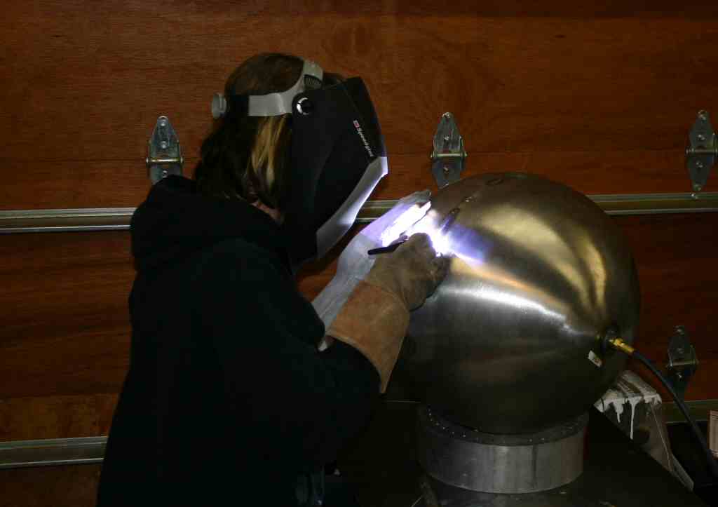
Carl at FloMetrics recommended a local gentleman named Bob to help us with some aluminum welding. Tonight my son went to his shop and held things while Bob welded up an aluminum tank with our hydro formed end caps. The quality of the work was very good, and we tested the tank this evening.

The Tank details...
  • Predicted Tank weight 5.6 Kg
  • Actual tank weight (The end caps ar a bit less deep) 5.25Kg
  • Predicted burst pressure: 558 PSI.
  • Actual tank burst 495 PSI. (End cap was too thin from forming.)
  • Calculated Tank volume disreguarding 1/2 the end cap volume to account for shallower than spherical end caps: 51.3 liters
  • MR 10.78
A picture of the burst tank end:


I'm very happy with this test. This is the exact tank design that is in my vehicle model
Bob was going to weld up a pair of tanks, but I think I'm going to have him hold off on the 2nd tank until I can hydro form some heavier endcaps of slightly thicker material. So we now have working valves, and a workable tank. Next up an ignitor, thrust chamber and paperwork.

Saturday, January 27, 2007

Normal Metal Tanks...

If I can't get my spectra tanks to work, I need a backup plan, toward that end we are fabricating two possible tanks. A Tank made out of aluminum thinwall tubing and hydro formed end caps. I spent Saturday fabricating end caps that will be welded to the aluminum thinwall tubing.
Here is a cap being formed in the forming fixture:


After pumping about 600 PSI water into the fixture the pressure is releived and the endcap is removed and put on the mill, indicated for center and then machined out of the blank.


The result is :


My son welded up the stainless hemispheres, and we tested these...


The first test sprang a leak at 450PSI in the weld, we patched that and it sprang a leak at 590 PSI, we patched that and it sprang two leaks at 710 PSI. All leaks so far have been in the weld area. The theoretical burst for this tank should be between 800 and 1300 PSI depending on if you give any stress credit for stretching the tank and work hardening it. So 710 is close to this value. The MR of this 18" tank is about 7.6 . The aluminum tanks we will weld up Sunday have a theoretical burst of 550 and an MR of 9.6.

Thursday, January 25, 2007

A plea for paperwork help.

I have negative amounts of tact and diplomacy when dealing with bureaucracy. If I think something is Bu****it I say so. I'm coming to realize that unless I get someone other than me to deal with the AST I'm not going to be successful. So what I'm looking for someone to do the following:
  1. Help me wade through the experimental permit process.
  2. Help me figure out exactly what technical supporting docs I need to prepare.
  3. Present this to the FAA/AST in my behalf.
If anyone is interested in working on this as a paid consultant please contact me. If I've already talked to you there is no need to respond again.

To contact me send E-Mail, you will have to answer to my SPAM filter.