Saturday, January 31, 2009

Planning the machining...

I spent a good part of the day double checking my motor design before I start machining the outside.I’m glad I did, because without some adjustments It would not have been possible to machine the cooling slots.I ended up making a 3D rendering of the motor, the slitting saw and the bottom eand of the mill spindle. Then I adjusted things until only the cutting surfaces contacted the motor.In the pictures below the tool and mill is represented via the Gold solid as it sweeps along its cutting path.


Ceckfit1


CheckFit2


Checkfit3


The last picture shows the general layout.


  • Blue is the slitting saw center line path.

  • Black is the chamber

  • Red is the cooling channel depth.

  • Purple is the outer jacket (made in three pieces then welded back together.

  • Green is the size of the raw stock that will form the outer jacket

Motorlayout

Monday, January 26, 2009

Inside Outside...

I know what the iinside of my chamber looks like, now to figure out the outside. I know what pressure drop I’m planning on at max flow in the jacket. So I need to figure out how many cooling channels and their width and depth. This is a bit of a black art so I drew up one pssible channel configuration and milled it as a slot in some aluminum. I then bolted a face plate against it. I put 18 PSI water pressure in one end and captured 10 seconds of flow that I weighed it was 390 gm. This was about 30 to 50% higher than I wanted. So I need to make them smaller, or reduce their number.  I also sent the cad model of my slot to my friends at flowmetrics and Carl was going to run a CFD check to see if experiment and simulation agree. The one big benifit to doing the simulation over the experiment is that it wont spray water on the front of your pants making the neighbors  think you had an accident. It will also allow one to do some proper heat flow analysis.


TestPlate


The test plate on the garage sink


Lathemount


The Lathe mount I worked on for several days. The boreing bar is 11” long to the face of the holder. This solid peice replaces the rotatable stock secondary slide. (Look up a birmingham or grizzly 13x40 lathe for a picture)


Lastly the motor insides I bored out of solid block of aluminum:


Regen_h2O2


All Day...

My new Lathe parts work well, I finished them this morning and then  I spent remainder of the day machining the inside of a motor out of a solid chink of aluminum. I am basically taking a 8” x 16” Solid aluminum round and removing everything that does not look like a rocket motor. I started at 9 am, its 1am a 18 hour day in the shop  on hard concrete. My feet hurt.

Friday, January 23, 2009

Just checking in

Since the ring catalyst failed we are evaluating two other kinds. We are looking at traditional silver plated nickel and some metal monollytic catalysts. We have some samples of the metal monolyths we received from John Carmack and we hope to test them in a regen cooled engine capable of running in Monoprop or Biprop mode in a week or two.  I ordered the nickel screens and hope to fabricate a motor for that configuration in the next two weeks.


I’ve been working on machining the regen engine out of a large chuck of aluminum and the size is stressing the capabilities of my lathe. The Lathe is a manual lathe converted to CNC and the cross slide tool mount was not very rigid. I started more than a week ago to machine some new mounts and the speed control on the Mill motor started acting up. So I bought the Tormach speed control upgrade (stock on the new Tormachs) and Its a great upgrade. Now that is fixed, I’ve spend the last week machining new tool mounts out of large chunks of steel. they should be more rigid.  The mill is machining the last piece as I write this so I hope to get back to machining the actual motor on Saturday.  Machining Aluminum and the C145 copper is fun, Machining stainless is miserable, machining medium steel is some where in the middle, not as picky about feed rate as stainless, but still wears the tooling a lot faster than aluminum. 


On a side note I stick all the tools I use at the mill, draw bar wrench, vice wrench, chuck keys etc… to the back of the mill with some strong magnets.  With aluminum or Stainless this is not an issue, when machining  steel all the sharp chips stick to the tools making it a hazard to use them. No fun at all.


Sunday, January 11, 2009

Test Results: Ring Catalyst Fails.

The Ring catalyst failed to get good decomposition. I have video of lots of billowing steam as the partially decomposed peroxide falls on the concrete in the flame trench. I probably won;t post these as they aren’t very interesting.


We were out at FAR at the same time as the FloMetrics guys and their LR-101 rocket static test went well. 10 Second burns on both RP-1 and Biodiesel. These videos I will probably post when I get time to do so. The sound of a kerosene rocket is just different that than lox-alcohol, hybrids, solids, sugars, and mono props. They all have a different sound and the kerosene sound is very cool.

Friday, January 09, 2009

Static Test

Our stuff is packed we hope to do a static test of the new solid cataylist on Saturday.


Friday, January 02, 2009

Designing a chamber....

So you want to design a chamber, there are many ways to do this. My method is not real rigorous, but here it is.


First know what you want. For this example:


  • 90% peroxide /kerosene with a solid catalyst.

  • 915 lbs max thrust. (This is 125% of max weight for my notional 180 sec vehicle.)

  • 320 psi feed pressure (This is our hydro pressure /1.25)

  • Optimize for best eff at 475lbs thrust. (This is the mid point on a 180 second burn this number probably needs adjusting upward as more fuel is burned at the beginning of the flight)

  • Operate at FAR or Las Cruces, or the new Mexico space port about 4000 ft altitude. (12.4 psi)

Given a 320 PSI feed pressure we need to allocate some pressure drops, I’ll use 75 lbs in the cat pack and 20 percent in the injector /diffuser.  I got the 75 PSI from a  FMC peroxide catalyst pack design document.  I got the 20% from word of mouth and vague references in Sutton.


So the resultant max chamber pressure is (320–75)*0.8 = 260 PSI.


So at our desired optimum 475 lbs we have a chamber pressure of


Cpopt=(475*260)/915 = 134 PSI.


Next Ill run this through cpropep. I ran lots of cpropep runs to arrive at the 0.17g of fuel for 100gm of 90% peroxide. This is the final input file run:


Propellant X/Y
+466     0.90 g
+976     0.10 g
+797     0.17 g


FR
+chamber_pressure     134 psi
+exit_pressure         12.46 psi


The output is:


Thermo data file: thermo.dat
Propellant data file: propellant.dat
Computing case 1
Frozen equilibrium performance evaluation


Propellant composition
Code  Name                                mol    Mass (g)  Composition
466   HYDROGEN PEROXIDE (100 PC)          0.0265 0.9000   2H  2O
976   WATER                               0.0056 0.1000   2H  1O
797   RP-1                                0.0121 0.1700   2H  1C
Density :  1.228 g/cm^3
3 different elements
H  O  C
Total mass:  1.170000 g
Enthalpy  : -6420.12 kJ/kg


114 possible gazeous species
3 possible condensed species


                       CHAMBER      THROAT        EXIT
Pressure (atm)   :       9.663       5.463       0.848
Temperature (K)  :    2418.562    2205.550    1608.636
H (kJ/kg)        :   -6420.118   -6948.077   -8362.579
U (kJ/kg)        :   -7389.021   -7831.644   -9007.016
G (kJ/kg)        :  -36931.242  -34771.963  -28656.161
S (kJ/(kg)(K)    :      12.615      12.615      12.615
M (g/mol)        :      20.755      20.755      20.755
(dLnV/dLnP)t     :    -1.00000    -1.00000    -1.00000
(dLnV/dLnT)p     :     1.00000     1.00000     1.00000
Cp (kJ/(kg)(K))  :     2.50147     2.45427     2.27083
Cv (kJ/(kg)(K))  :     2.10086     2.05366     1.87022
Cp/Cv            :     1.19069     1.19507     1.21421
Gamma            :     1.19069     1.19507     1.21421
Vson (m/s)       :  1066.56503  1027.58281   875.97064


Ae/At            :                 1.00000     2.44989
A/dotm (m/s/atm) :               157.40662   385.62851
C* (m/s)         :              1520.94574  1520.94574
Cf               :                 0.67562     1.29592
Ivac (m/s)       :              1887.43319  2297.97666
Isp (m/s)        :              1027.58281  1971.02048
Isp/g (s)        :               104.78429   200.98815


Molar fractions


CO                   9.0878e-002 9.0878e-002 9.0878e-002
CO2                  1.2411e-001 1.2411e-001 1.2411e-001
COOH                 3.2035e-007 3.2035e-007 3.2035e-007
H                    1.6249e-003 1.6249e-003 1.6249e-003
HCO                  2.3091e-007 2.3091e-007 2.3091e-007
HO2                  1.8081e-007 1.8081e-007 1.8081e-007
H2                   8.5414e-002 8.5414e-002 8.5414e-002
HCHO,formaldehy      3.0941e-008 3.0941e-008 3.0941e-008
HCOOH                2.3185e-007 2.3185e-007 2.3185e-007
H2O                  6.9535e-001 6.9535e-001 6.9535e-001
H2O2                 1.3262e-007 1.3262e-007 1.3262e-007
O                    3.1412e-005 3.1412e-005 3.1412e-005
OH                   2.4808e-003 2.4808e-003 2.4808e-003
O2                   1.0559e-004 1.0559e-004 1.0559e-004


Lots of data here but I really only want the four items I set in bold.


First dimension question how big is the throat?


For 915 lbs thrust at 260 PSI we need the Cf number.


So Throat Area = 915/(260*cf) =2.71 sq inches in area.


The Throat diameter is thus 1.859473 inches.


For thoose who want consistent SI units:


915 lbs is 4080 N  260psi is 179 N per cm^2


So At = 4080/(179*cf) = 17.58 cm^2


converting back to inches for a consistantcy check we have 2.72 sq in.


Now that we have the Area Throat we need Area Exit


Ae=(At*Ae/At) =2.71*2.44989 =6.65 sq in and a diameter of 2.9147 inches.


So now we have the Throat diameter and Exit diameter.


We need the chamber length. This chamber will have Gas/Liquid mixing so we can probably use a shorter chamber than usually, but I’m going to be somewhat pessimistic and use a L* of 50in. I’m also using some fixed catalysts at 7” so my chamber inner diameter is going to be 6.5”.


6.5” diameter is 33 sq in. The At =2.71 so 2.71*50/33 = 4.1 inches.


We now have the major dimensions of the chamber done.


  • Throat 1.859 in diameter

  • Exit 2.915 in diameter

  • Chamber 6.5 in diameter

  • Area before the throat 4.1 in long.

The Now to draw some shapes. One could use the classic 15 degree exit cone that would be easy to machine, but gives up a few percent performance. Or one could try and do a parabolic expansion cone. I used the RAO optimum nozzle approximation. This is covered in Rao’s classic paper or texts like Modern Engineering for design of Liquid propellant Rocket Engines (Huzel/Hwang) . This requires that you pick a couple angles off a graph and fit a parabola to the resultant points. The problem is actually over specified so you have to decide which end of the parabola you want to be exact. The cook book formula gives you 4 equations and 3 unknowns. For the more math inclined you have two specified points and the slope at both points and you want to fit a 2nd order parabola through these. Like I said over specified. (You can see the document in question by doing a google book search look at page 76. Search for Huzel Hwang) So after getting some advice and a code snip-it from arocket I wrote a short program that fits a parabola to the defined points . I assumed a 100% of conical length.


So I drew the chamber in the following steps….


  • Placed a reference  point at 0,0 and one at 0,(1.859/2) (black)

  • Drew an Arc of 1.5 rT to 60 degrees (red)

  • From the chart Fig 4–16 initial angle is ~20 degrees. So I drew an arc blue of 0.382 Rt to 20 degrees.

  • Then I placed a point at the exit position. A 15 degree half angle cone would be 1.97 inches long going from 1.859 to 2.915 inches. So I plot this point referenced from the throat. (Green line)

The result at this point:


ChamberStep1


Now using my CAD program I read the x,y locations for the end of the blue arc:


Point at (0.239756,0.971775,0). And the end of the green line. Point at (1.97,1.4575,0).


I plug all this into my little program and calculate a script to draw the nozzle. The Program :File Attachment: calcv2.cpp (1 KB). Now I have the basic chamber contour. All I need to do is Add the upper chamber and mirror


LP180CpOutline


Next steps involve giving the chamber some thickness and the design of the catalyst holders and injector/diffuser seals connections etc…. to be continued….


Friday, December 26, 2008

Merry Christmas

I won’t be blogging much until early next year. There is a possibility we may static test our new motor sometime between 31st and 4th. I’m looking forward to more progress in 2009.  The gear box is 90% done I need to make one more bearing plate, but all the major structure is done. All the rotating parts are done. It’s heavier that I would have liked. When I’m done I will fully disassemble and weigh the individual parts.


Gearbox2GearBox3


Sunday, December 21, 2008

Why I like this project....

There is very little I enjoy more than learning something new. A traditional aerospace project is an effort involving thousands of specialties. This offers the opportunity to learn thousands of specialties. I have received my Peroxide compatible pump, fuel pump, and motor. I’m in the process of assembling a gear box. I’ve never built a gear box before so one gets to learn new terms like pressure angle and involute. As well as use new tools.. I’m continuously impressed with the variety of free tools available on the web. I’d gathered all the shafts, bearings, gears, parts and etc in to a big pile on my desk. I spent the better part of yesterday laying out the gear box.


I have a fully 3d capable cad system, but I usually do my layouts as 2D line drawings. I find this easier than making a 3D model. My gear box sketch is below as I have been using it (Labels added for your viewing pleasure)


Gearboxv2


File Attachment: GearsV2.pdf (24 KB)


I’ve machined the top base plate, the adaptor that joins the peroxide pump to the base plate and the curved offset spacers. (Only shown in top view the semi circular arcs with screw holes ).  Today I’m going to try and build the complicated shaft that connects the two pumps to each other and to the gear drive. I’m also going to finish bore the gears and lighten them. If all goes really well I may even get to a full trial assembly.


Gearboz


This shows the peroxide pump and the aluminum adaptor connecting it to the main plate. It also shows the curved spacers.


Monday Morning update. I machined the shaft and couplers for the pump side , I also lightened he commercial gears and bored the one that needed bored.


Friday, December 12, 2008

Back to Hardware....

We are   were going to go out to the test site and static test the blue ball with a “solid” catalyst. (The FAR event was canceled due to 75mph winds forecast on Saturday as I was typing this.)


John Carmack sent me several catalyst styles, one kind was a pourable ring catalyst from cpilink.com It looks like the picture on the right here. So we had some stainless plates  water jet cut by Thunderbird Water Jet to hold the catalyst rings, and we added a sintered stainless diffuser plate. and reassembled the motor.


Stainless motor 003


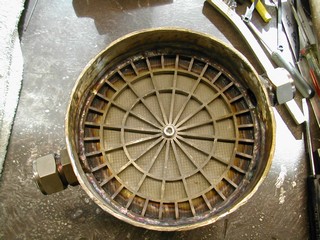
When we first cut the motor apart the inside was kind of nasty with permangenate residue.


Catalyst motor 001


A picture of the sintered diffuser plate welded to the support ring.


Catalyst motor 003


A view from the other side as it is welded into the top of the motor.


Catalyst motor 007


A view of the waterjet cut bottom support plate. The area between the two plates is filled with the ring catalyst. The fittings on the side as shown on the view of the motor top allow us to shake the catalyst out and replace it.


Catalyst motor 009


The reassembled motor ready for testing…. soon.

Wednesday, December 03, 2008

New FAA rules.

The new FAA amateur rules were released today. It looks like they will be officially published on the 4th and become effective on Feb 2nd.  Since this removes the burn time limit and requires nothing more than ATC notification for flights in  uncontrolled airspace more than 5 miles from an airport, it basically means ZERO paperwork for the testing and development of a hovering LLC class vehicle that stays under 200K lb/secs of total impulse.  I’m practically giddy!

Monday, November 24, 2008

Thanksgiving week...

While we all enjoy the company of friends and family during this thanksgiving holiday, don’t forget the men and women of our armed forces that may not get the chance to be home this holiday season. I’ve given something to LBEH for the last 7 years to try and help. Some bloggers have a tip jar, I ask that you send any tips there instead.


Offical comments on 2009 LLC


See http://thelaunchpad.xprize.org/2008/11/2009-lunar-lander-challenge.html

Friday, November 21, 2008

A Quick update...

My next rocket project is to finish up some test stand work for a paying customer I can’t talk about.


As for the LLC projects :


I’ve been exploring a number of catalyst options for peroxide. I’m looking at silver plated nickel screens, and commercial catalysts from several different vendors. These include the commercial catalysts from CPILINK that John Carmack was kind enough to send me. If that catalyst is still commercially available then its high on my list. All of the parts and pieces to build an electrically pumped biprop peroxide test have been ordered. I have all the parts on hand to both convert the 90 Second vehicle to a solid catalyst and to build a biprop version of very similar design capable of doing 180 seconds.


The plans for next years LLC have stirred a bit of controversy and I’m not sure what side of the debate I agree with. The basic problem is this: The LLC is supposed to be an impartial contest, yet you have the head of the Xprize, Peter on video telling John Carmack that they will expedite the 2009 contest so Armadillo does not have to wait a full year to win the prize. That was an astonishingly ill conceived video. Peter has a personal business relationship with Armadillo, so even if there are a million legitimate reasons to accelerate the contest and change its format, that one video could be used by anyone with an axe to grind to trash both the concept of government prizes and the xprize organization in particular.


I’d really like to see the 2009 LLC be a first to demonstrate at any location like the original Xprize. This would simplify the contest for all competitors as you would only have to get permission to fly in one location, not both your testing base and the LLC venue. It would also reduce the financial burden on the xprize organization as the local logistics would be resolved by the team and not Xprize. From a personal stand point It would improve our odds of winning the 2nd place 90 second prize and enable us to then switch our focus to taking a shot at the 180 2nd place prize when we were ready rather than at some specific date. . Unfortunately I’ve personally received enough private E-mail from multiple people just steaming mad about this that I can’t see the possibility of any change in the LLC format without it ending up in court.


The sad part about this is that after spending two years working on this I have a feel for the difficulty level and I don’t see that any of the new not yet flown teams have a shot at getting a 180 second vehicle ready by October, its just too hard. Other than armadillo we are the only currently registered team that has fired a motor to thermal equilibrium with the necessary performance to do 180 seconds (Our Lox Ethanol motor) and we have chosen to take a different direction.

Monday, November 10, 2008

Plans...

90 Second Vehicle.


John Carmack was really kind and sent me some peroxide catalyst material Armadillo was no longer using. I’m going to rebuild the present motor with these cataylsts. I’ll try to provide some pictures. I’ve ordered some stainless parts and some sintered stainless screen to spread the peroxide out. I figure about 4 days of work and this will be ready.


Things to fabricate /do:


  • Fabricate New Motor upper section.

  • Revise my safety plan with no liquid catalyst and get the waiver extended/approved for this configuration.


180 Second Vehicle. #1


We have a pressure fed 180 second airframe 95% fabricated.  It will be a Peroxide RP1 biprop. To finish this vehicle we need to design a chamber and  switch to thrust vector controls. If we get the same percentage of theroretical perfomance as we got with our monoprop vehicle this will hover for about 195 secondds in blow down mode. If we put active presurization on the vehicle it will hover for 240 seconds. My friend Steve Harrington of Flometrics is dying to try out a liquid nitrogen presurization system modeled after the liquid helium system on the origional apollo lunar lander system.  So if we don’t quite get there from a performance stand point with blow down we will add this Ln2 system.


Things to acquire fabricate/do for this vehicle:


  • Fabricate a regen chamber. Currecnlty working on an aluminum design, have stainless and nickel designs sketched out, but will try aluminum first.

  • Fabricate TVC controls, both Masten and Armadillo are using Bug actuators, a bit pricey, but I’ll probably go that way.

  • Fabricate  valves usign the existing valve design(s) we have.

  • Start the paperwork process so we can do tethered flights in Jan/Feb time frame.


180/300 Second vehicle concept development work:


I’ve done a lot more modeling of a 4 engine electrically pumped vehicle. I really like the results I’m seeing. Even more I like the fact that the propulsion is almost 100% decoupled from the tank design.We are going to go ahead and purchase one set of parts to build 1/4 of the propulsion system. I’ve found a vendor for a positive displacment peroxide compatible pump that is the right size for a 4 engine pumped vehicle.I’ve alos found a vendor for the the motor and speed control of the approriate size.  If this works the parts could be easily transfered from a hovering  LLC vehicle to a 100Km+ capable reusable suborbital sounding rocket. If the all the LLC $$ had  been won this would be my primary project.  If this sounds interesting to anyone my priorities can be altered with the proper application of funds ;-)


Things to change in the flight test program:


The Rough terain forklift worked really well so it is going to return for an encore performance. Since construction is slow in california the rental prices have really fallen. One problem with the testing I did for the 90 second vehicle was the cost of each full fuel test. I’m going to modify the vehicle(s) to carry lead bricks to simulate a full fuel load. This way I can verify I have the necessary propulsicve performance without burning up 2K of peroxide for each test. I can put in a single Jug of peroxide and time the hover with the weight and know if I have the proper performance.


Monday, November 03, 2008

Lessons Unlearned

In 2007 we tried to build a 4 engine Lox Ethanoal rocket. When we were done it had 39 valves and was just wayyyy too complicated to work reliably. My present 180 second fantasy goes back in that direction a tiny little bit. If youmake the following assumptions:


  • Electrically driven peroxide and RP-1 pumps.

  • Catalyst decomposition with lots of pressure drop for relability

  • 1000 to 1200 PSI feed pressure

  • 700–800 PSI chamber presure.

  • Four engines.

  • 80% of theoretical ISP.

Then what drops out is


  • Off the shelf small aluminum frame hydralic pumps (Possibly with one section redone with stainless gears)

  • Off the shelf  Pump motors,batteries and gearing from  high end 600 sized RC helicopters.

  • Hover times of 240 seconds+ with payload.

  • A rocket with two manually operated valves (Vent and drain)

  • Tanks with a pressure safety factor >4 so humans can be near the presurized rocket.

  • A rocket with no active valves. (All control is from the pump speed control)

  • Precise Mixture control.

  • Safety system is all electrical, power stops to motors and down it comes.

I’ve ordered a pump to evaluate its peroxide compatibility and life time running unlubricated.  The pump was only $72.

Thursday, October 30, 2008

Level 2 is hard

A lot of people have advised me to ignore the 180 until the 90 is in the bag. Its probably good advice, but I’d like to start doing some 180 second development tests when we go out to the site to test the 90 second vehicle. The trip to the test site is a significant portion of the time involved with a test and so I’d like to use that time for testing both if possible.  I did a very detailed model last night. I started with the following assumptions:


  • It needs to stay as an amateur vehicle IE total impulse < 200K lb/sec

  • I’ll use an off the shelf LR-101 as the motor

  • I’ll use the same AMS industries Spun 5086 aluminum hemispheres for tankage that we used for the 90 second vehicle.

  • I’ll assume that the LR-101 ISP starts at 200 at design Cp and degrades along the same slope as Cpropep down to the minimum Cp (Cpropep says LR-101 should give 230 Isp at design pressure) This discrepancy is probably because the LR101 is significantly over-expanded at sea level.

I included in the model:


  • Pressure Drops in the LR-101 Jackets, and Injectors

  • Isentropic Gas expansion in blow down mode.

Given these assumptions I could not build a 180 second vehicle. so I modified the assumptions:


  • Add one Carbon fiber SCI 602 presurization bottle and Regulator to use on the LOX side. Allowing us to  fill the Lox sphere  past the point where blow down mode would run out of pressure.

Given these assumptions the model says we can hover for 200 seconds.


This probably won’t work for the following reasons:


  • The motor is WAAAY over-expanded for the entire flight. We could use all the LR101 dimensions and injector and build a motor that has the same internal dimensions and lower expansion ratio. this would likely give us back some ISP, but we are no longer off the shelf.

  • The motor needs to throttle 4:1 and as the pressure drop in the injectors goes down that low then we probably don’t get good mixing.

  • The outcome is really sensitive to the initial loading conditions over/under filling the Lox tank by 5% causes a 10 second change in the hover period.

  • We need to get the same hydro test performance out the tanks as Armadillo is getting and our first tank was 25% low, we have not yet been brave enough to test the 2nd tank to the level we need.

  • It would be really hard to keep the mixture ratio matched exactly over a 4:1 throttling ratio without really good closed loop controls.

  • The LR 101 is hard to get lit.See the SDSU rocket at 1:42 into http://www.youtube.com/watch?v=Wzl_IaSJx28 

Some additional thoughts on the 180 second problem:


If I use different sphere sizes and thicknesses and put on lots of pressurant bottles I can get my detailed model to say we hover for 230 seconds, but the same issues identified above apply.


The 180 second level 2 is all about getting good mass ratio and ISP. For non-pumped systems the density of the propellants really matters. I’m using 1.1 as my Lox density 0.8 as my RP-1 density. I really think Peroxide would be better, 90% peroxide has a higher density than Lox 1.36, and it also makes up a higher percentage of the total propellant load so the portion of your propellant at 0.8 is lower. I’ve seen Density * Isp ^2 as a figure of merit (FOM) in SSTO studies.


Examples :


  • Peroxide RP1 at 200 PSI running at best ISP has ISP 215.6 and Density 1.246 FOM: 58K

  • Lox RP1 running at LR-101 mixture ratios and 200 PSI has ISP 219 and Density 0.993 FOM: 48K

  • Lox RP1 running at best ISP and 200 psi  has ISP 230 and density 1 FOM: 53K

You are much more likely to get the peroxide motor running at peak ISP to cool in regen mode as there is much more cooling fluid available with a much higher heat capacity. Its clear the LR-101 designers with an infinite budget did not choose to give up 10 points of ISP with out trying.


One LLC competitor that had a static display at the 2006 xprize cup, had a system with electrically driven positive displacement pumps using peroxide, liquid catalyst and a fuel. this insures constant mixture ratios across the entire throttling range and makes your FAA safety system really easy as you just have a power relay that drops power to the pump and all propellant flow stops. Your tank thicknesses  are set by minimum gage issues not pressure requirements.  If one developed this it would also be easily transfered to vehicles with more aerodynamic tankage than the big spheres. (Space here we come….)

Monday, October 27, 2008

You know rockets have taken over your life when...


You know that rockets have taken over your life wihen the Google street view of your house has the truck parked in front with a rocket test stand and an empty LOX dewar in it. We never parked there with a full dewar. The combination of things in the truck puts the picture between May and Sep of 2007 The real estate sign is not for our house.

Sunday, October 26, 2008

Performance Dreams and Spread sheets....

According to Propep 85% peroxide has the following “frozen” ISPs at our altitude.


  • 250 PSI :125

  • 162.5 PSI 118

  • 75 PSI : 103

Our realized ISP was about 83.


If we had gotten 90% of the lowest number: or 92.7 we would have hovered for 99 Seconds.


Checking Cpropep  against the FMC peroxide manual we get 130.32 (propep) compared to their 129.0 comparing like to like. (250 PSI 90%, 1ATM Pe)


So one possibility is that we switch to a solid catalyst. This sheds some weight, but lowers chamber pressure for the same tank pressure…. crunchingg the ISPs second by second as the chamber pressure goes from 220 down to 72  assuming 80% of theoretical performance we get 100 seconds. Assuming 100% we get  124


If we bump from 85% to 90% HTP and switch from N2 to He for our presurant (Our back up reserve boosters) still assuming 80% of theoretical we get 109 seconds.


One of the problems is that if you set the expansion ration so you are good at your lowest presure you are kind of stuck with that ISP for the whole flight. So you plan on running underexpanded for 50% or so of the flight. I’ve not found a good way to model performance underexpanded.


Friday, October 24, 2008

Condolences to True Zero and Congratulations to Armadillo.

Condolences to True Zero and Congratulations to Armadillo.

I have mixed feelings about TrueZero, I know the agony they are feeling, yet I'm a little bit personally relieved that I made the right choice to not compete this year.

Armadillo's third years the charm! Armadillo did 1/2 the task at the contest at least 5 times (I've lost count) before winning, they really deserved the win.
Now on to Level 2.....